

Loading device and method for stretch dynamic load test of self-sealing type shedding joint
A loading device and dynamic load technology, applied in the field of dynamic load test, can solve the problem of complex force transmission path of the lever loading mechanism, achieve the effects of reducing the cumulative effect of damage, convenient operation, and simple structure of the device
Active Publication Date: 2019-08-06
NANJING UNIV OF AERONAUTICS & ASTRONAUTICS
View PDF20 Cites 7 Cited by
- Summary
- Abstract
- Description
- Claims
- Application Information
AI Technical Summary
Problems solved by technology
For example, the invention patent "Anchor Dynamic Tensile Experimental Device and Experimental Method" (authorized announcement number: CN 105510158 B) converts and amplifies the impact load into a tensile dynamic load, and the force transmission path of the lever loading mechanism used is relativ
Method used
View moreImage
Smart ImageViewing Examples

Examples
 PUM
 Abstract
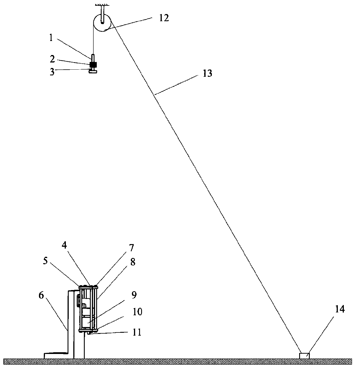
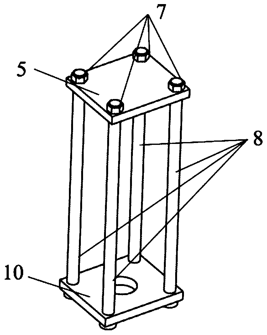
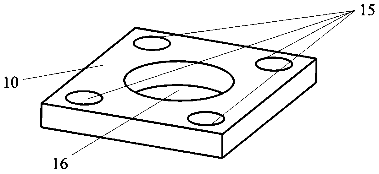
The invention, which belongs to the technical field of dynamic load testing, relates to a loading device and method for a stretch dynamic load test of a self-sealing type shedding joint. The loading device comprises a rigid base, a transmission platform, a loading platform, a rigid screw connecting the loading platform with the transmission platform, a drop hammer, an acceleration sensor, a dynamic load sensor, an adjustment mass block, variable-thickness rubber pads for adjusting load acting time and values, a positioning pulley, a flexible rope, and a pressing block for fixing the flexible rope. According to the invention, the loading device has advantages of simple structure, great convenience in processing, and great convenience in operation. Compared with the existing reported stretchdynamic load device only emphasizing acquisition of stretch load information, the provided loading device pay attention to three factors including the stretch dynamic load acting time, a fixture speed changing amount, and a load size and coordinates the coupling effects of the three factors, thereby completing the test task effectively. Therefore, the loading device and method have the importantengineering significance in determining the stretch disconnecting dynamic load of the self-sealing type shedding joint.
Description
technical field [0001] The invention relates to a loading device and method for a tensile dynamic load test of a self-sealing shedding joint, belonging to the technical field of dynamic load tests. Background technique [0002] When the aircraft crashes and there is a risk of crash, in order to reduce the additional damage (such as fire, etc.) caused by the fuel leakage in the aircraft fuel pipeline, it is necessary to use a self-sealing drop joint to seal the oil pipeline. In order to prevent accidental loading during flight or maintenance from affecting the joint, it is required that the disconnection load of the shed joint be greater than the service load of the connection position and less than the failure load of the tubing itself. Considering that the tensile load is the main force bearing mode of the oil pipe and its joints, the tensile breaking dynamic load of the self-sealing shedding joint should be determined first to ensure that it meets the service requirements....
Claims
Login to View More Application Information
Patent Timeline
 IPC IPC(8): G01N3/303G01N3/06
CPCG01N3/303G01N3/06G01N2203/001G01N2203/0039
Inventor 邓健周光明徐庆华
Owner NANJING UNIV OF AERONAUTICS & ASTRONAUTICS