Supercharge Your Innovation With Domain-Expert AI Agents!

Disc motor winding

A disc motor and winding technology, which is applied to the shape/style/structure of the winding conductor to achieve the effects of high tensile strength, large winding cross-sectional area, and easy insulation gap.

Active Publication Date: 2019-08-06
SHANGHAI UNIV
View PDF15 Cites 4 Cited by
  • Summary
  • Abstract
  • Description
  • Claims
  • Application Information

AI Technical Summary

Problems solved by technology

[0007] In the above existing technologies, it is not possible to improve the space utilization rate and temperature characteristics of the winding, and it can be applied to the winding topology of the disc motor with or without slots.

Method used


Image

  • Disc motor winding
  • Disc motor winding
  • Disc motor winding

Examples


Embodiment 1

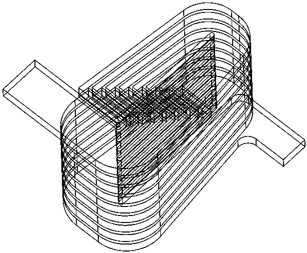
[0038] see Figure 1 to Figure 6 , the disc motor winding is characterized in that: each phase winding adopts a variable cross-section structure, and the radial cross-section gradually increases from the inside to the outside; the windings of the variable cross-section units are connected through progressive connections to achieve layered arrangement to form a winding Basic parts; the winding basic parts are covered with insulating materials or high-strength supporting materials to improve the insulation level and structural strength; the winding basic parts in different helical directions are connected according to the actual winding arrangement principle to form the stator windings of each phase, providing the time required for the direction. Variable magnetic field; the winding structure of the disc motor has strong adaptability and is suitable for slotted and slotless disc motors. The winding of the disk motor described in the invention has simple structure, high strength,...

Embodiment 2

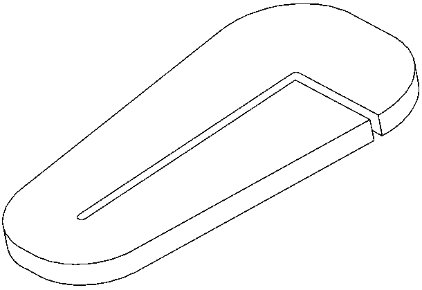
[0039] Embodiment 2: This embodiment is basically the same as Embodiment 1, and the special features are as follows: the unit winding of the disc motor winding ( figure 1 ) is a winding with variable cross-section, that is, the cross-section near the inner circle of the winding is smaller, and the cross-section near the outer circle of the winding is larger.

[0040] Sections of the unit windings include, but are not limited to, rectangular windings, circular windings, and the like.

[0041] The unit winding includes, but is not limited to, it is made of a whole piece of conductive material by wire cutting, or it is made of multiple pieces of conductor material welded, or it is made of a whole piece of conductor bent. The center gap of the unit winding can be determined by the actual required creepage distance Depends on the level of insulation.

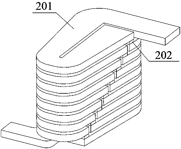
[0042] In particular, the unit windings can be formed by progressive connections ( figure 2 ).

[0043] The progressive connect...

Embodiment 3

[0050] Embodiment three, this embodiment is basically the same as embodiment two, and the special features are as follows:

[0051] The disk motor winding structure and its manufacturing method are suitable for slotted disk motors. The size of the central gap of the unit winding is determined by the structure of the stator slot.


PUM


Abstract

The invention discloses a disc motor winding. The disc motor winding adopts a variable cross-section structure, and the radial cross-section gradually increases from inside to outside. The unit winding processing technology includes, but is not limited to, wire cutting, bending and welding. The variable-cross-section unit windings are connected by progressive connection, and are arranged in a layered manner to constitute basic winding components. The basic winding components can be covered with an insulating material and a high-strength supporting material to improve the insulation level and structural strength. The basic winding components in different helical directions can be connected to form stator windings of different phases according to the actual winding arrangement principle to provide a time-varying magnetic field in the required direction. The disc motor winding structure has strong adaptability, and can be applied to disc motors with and without slots. The disc motor winding of the invention has the advantages of simple structure, high strength, excellent thermal performance and high utilization rate of winding space, and can enhance the power density and torque density of disc motors.

Description

technical field [0001] The invention belongs to the field of motor design and manufacture, and in particular relates to a disc-type motor winding. Background technique [0002] The overall structure of the permanent disk motor is compact, which is conducive to the improvement of the torque density compared with the radial magnetic field motor. The disc motor has a short axial dimension, a large outer diameter, and a flat body. It is often used in applications where the axial dimension and volume are limited. [0003] Disk motors have the advantages of small size, light weight, high torque density and high power density, but have limited cooling and heat dissipation capabilities. If the temperature of the winding is too high, it will cause insulation damage; if the temperature of the permanent magnet is too high, it will cause performance degradation or even irreversible demagnetization, which directly affects the efficiency, reliability and service life of the motor. How t...

Claims


Application Information

Patent Timeline
IPC IPC(8): H02K3/04H02K3/28
CPCH02K3/04H02K3/28
Inventor 罗建王越韩清江徐天蔚李柏杨
Owner SHANGHAI UNIV
Features
  • R&D
  • Intellectual Property
  • Life Sciences
  • Materials
  • Tech Scout
  • Unparalleled Data Quality
  • Higher Quality Content
  • 60% Fewer Hallucinations
Learn More