Blade spray protection fixture, blade spray protection method

A technology of protective clips and blades, which is applied in the direction of coatings, spraying devices, and devices for coating liquid on the surface, can solve the problems of no effective protection means, achieve effective spray protection, high pass rate, and reduce the cost of spray protection Effect

Active Publication Date: 2020-07-24
CHINA HANGFA SOUTH IND CO LTD
View PDF9 Cites 0 Cited by
  • Summary
  • Abstract
  • Description
  • Claims
  • Application Information

AI Technical Summary

Problems solved by technology

[0005] The invention provides a blade spraying protection fixture and a blade spraying protection method to solve the technical problem that there is no effective protection means for the complex profile parts of the citron plate and the grate tooth of the turbine working blade

Method used


Image

  • Blade spray protection fixture, blade spray protection method
  • Blade spray protection fixture, blade spray protection method

Examples


specific Embodiment

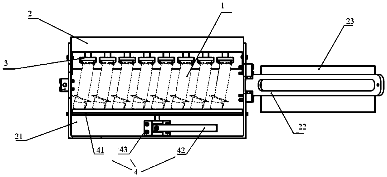
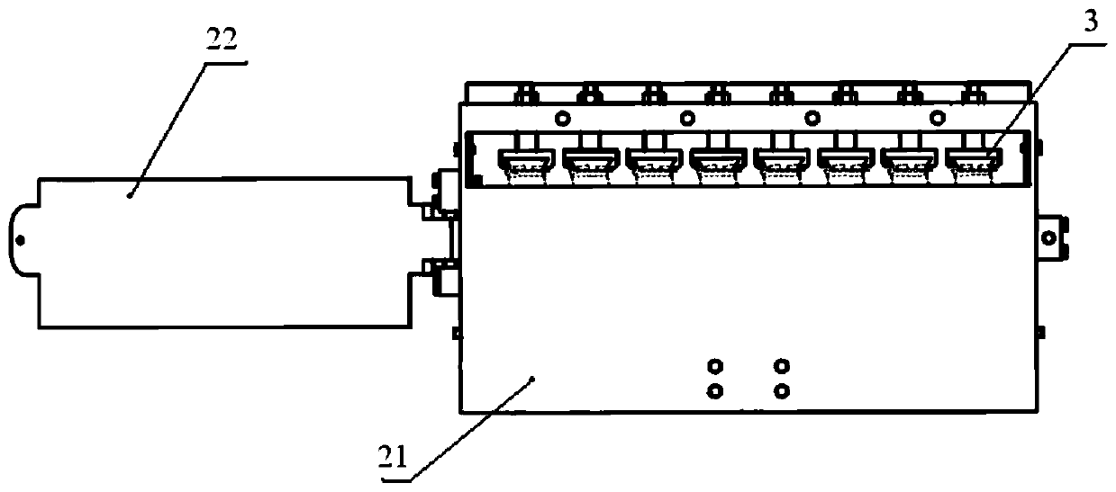
[0043] Blade spray protection fixture, including frame body 2, glue, slider 3, and pusher 4, the glue is located in the slot of slider 3, the slot of slider 3 faces the pusher 4, there are 8 pieces of glue and slider 3 respectively; the frame body 2. It includes a main frame 21 and a pressure plate 22. The main frame 21 and the pressure plate 22 are connected by shafts and positioned by screws. The pressure plate 22 is provided with a stopper 23, and the main frame 21 is provided with an upper stopper on which the slider 3 is installed and fixed. The upper stopper is threadedly connected with the slide block 3, and the main frame 21 is provided with a chute; the pusher 4 includes a push plate 41, which is connected to one end of the screw rod, and the other end of the screw rod is connected to a nut sleeve, and the nut sleeve is fixed on the main frame through the support. On the frame 21 , the nut cover is connected with the torsion bar by screws, and the torsion bar is rotate...


PUM


Abstract

The invention discloses a blade spraying protection fixture and a blade spraying protection method for fixedly clamping blades to be treated and protecting blade crown parts of the blades. The blade spraying protection fixture comprises a frame main body for fixedly clamping blade molded surfaces and spraying blade sprayed areas; the frame main body is provided with a slide block with a notch anda peripheral degree of freedom; the slide block is filled with plaster for protecting the blade crown parts of the blades; and the frame main body is provided with a pushing piece distributed oppositeto the slide block and used for matching with the slide block to axially clamp the blades. In the blade spraying protection fixture, the blades are clamped on the frame main body; the blade crown parts of the blades are pushed into the plaster in the slide block through the pushing piece; and the plaster is tightly attached on the blade crown parts of the blades for protection. The blade sprayingprotection fixture achieves effectively spraying protection on edge plates and comb teeth at the blade crown ends of turbine working blades, and improves the coating quality.

Description

technical field [0001] The invention relates to the field of spray protection of aviation turbine blades, in particular to a blade spray protection fixture. In addition, the present invention also relates to a blade spray protection method comprising the above-mentioned blade spray protection fixture. Background technique [0002] In the process of thermal spraying, the protection of parts before spraying and the cleaning after spraying are relatively important links, and they are also the most time-consuming and manpower-consuming links. For example, the working blade of a turbine of a certain type needs to be sprayed with a layer of wear-resistant coating on the blade crown, and the other parts of the blade should not have redundant objects during the spraying process and need to be protected. Due to the particularity of spraying, after spraying, the adjacent area of ​​the blade shroud will have some residual coating, so the adjacent area of ​​the blade shroud needs to be...

Claims


Application Information

Patent Timeline
Patent Type & Authority Patents(China)
IPC IPC(8): B05B13/02B05B12/28B05D1/02B05D3/02
CPCB05B12/28B05B13/025B05D1/02B05D3/0254
Inventor 张远应云海涛郑南松谭飞郭志宏陈建强张志远
Owner CHINA HANGFA SOUTH IND CO LTD
Why Eureka
Try Eureka