An auxiliary mold for side positioning

A mold and gear technology, applied in the field of auxiliary molds for side positioning, can solve the problems of difficult batch stamping production, affecting molding quality, and low work efficiency, and achieve the effect of improving utilization rate, simple structure, and good use effect

Active Publication Date: 2021-01-08
西安威尔精密技术有限公司
View PDF6 Cites 0 Cited by
  • Summary
  • Abstract
  • Description
  • Claims
  • Application Information

AI Technical Summary

Problems solved by technology

Stamping dies are very important in stamping. Without a stamping die that meets the requirements, mass stamping production will be difficult; The existing stamping die does not have a structure for positioning and restricting the material plate to be stamped, so that when the material plate to be stamped is continuously stamped by the stamping die, it is easy to cause the deviation of the punching route and affect the forming quality; Electric push rods are used to position material plates, but in order to adapt to different material plate widths, the electric push rods on both sides of the material plates need to be adjusted at any time; it is very difficult to adapt to different widths of material plates through frequent adjustments to the electric push rods. Troublesome and inefficient

Method used


Image

  • An auxiliary mold for side positioning
  • An auxiliary mold for side positioning
  • An auxiliary mold for side positioning

Examples


Embodiment Construction

[0033] The accompanying drawings are all schematic diagrams of the implementation of the present invention, so as to understand the principle of structural operation. The specific product structure and proportional size can be determined according to the use environment and conventional technology.

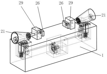
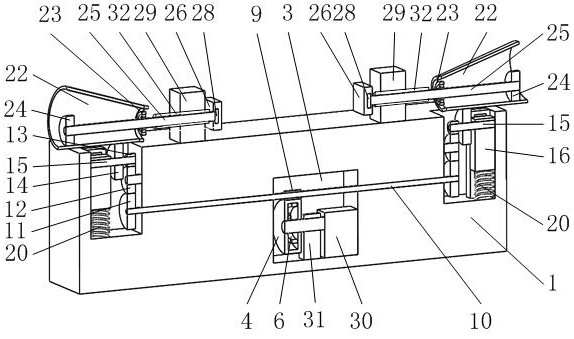
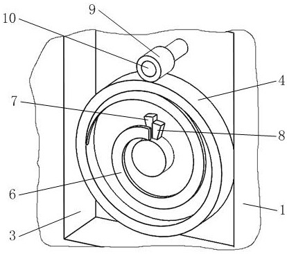
[0034] Such as figure 1 , 2 As shown, it includes a base 1, a gear A4, a scroll spring 6, a gear E13, a friction wheel 14, a shaft B15, a slider 16, a pressure spring 20, a clamping mechanism 21, and an electric drive module 30. figure 2 , 3 As shown in , 10, an electric drive module 30 is installed in the transmission groove B3 on the base 1, a gear A4 and a scroll spring 6 are installed on the output shaft of the electric drive module 30, and the scroll spring 6 resets the movement of the gear A4; Such as image 3 As shown, the block A7 installed on the side wall of the gear A4 cooperates with the block B8 installed on the output shaft of the electric drive module 30; fig...


PUM


Abstract

The invention belongs to the technical field of stamping dies, and in particular relates to an auxiliary die for side positioning, which includes a base, a gear A, a scroll spring, a clamping mechanism and an electric drive module, etc., wherein the transmission groove B on the base is installed There is an electric drive module, the output shaft of the electric drive module is equipped with a gear A and a scroll spring, and the scroll spring resets the movement of the gear A; the two clamping mechanisms in the present invention can carry out clamping on both sides of the material plate to be punched. Clamping, so as to fix the position of the material plate, so that it will not be shifted during the stamping process, improve the utilization rate of the material plate to be stamped, and increase the number of stamped products per unit area of ​​the material plate; the electric drive module is in a single operation During the process, the number of rotations of the output shaft is constant; there is no need to repeatedly adjust the number of rotations of the electric drive module to adapt to different widths of material sheets, which simplifies the automatic control system and improves work efficiency at the same time.

Description

technical field [0001] The invention belongs to the technical field of stamping dies, in particular to an auxiliary die for side positioning. Background technique [0002] Stamping is a forming processing method that applies external force to plates, strips, pipes and profiles by presses and molds to cause plastic deformation or separation to obtain workpieces (stamping parts) of required shape and size. The mold used for stamping is called stamping die, or punching die for short. Die is a special tool for mass processing materials (metal or non-metal) into required punching parts. Stamping dies are very important in stamping. Without a stamping die that meets the requirements, mass stamping production will be difficult; The existing stamping die does not have a structure for positioning and restricting the material plate to be stamped, so that when the material plate to be stamped is continuously stamped by the stamping die, it is easy to cause the deviation of the punchi...

Claims


Application Information

Patent Timeline
Patent Type & Authority Patents(China)
IPC IPC(8): B21D28/14B21D28/04B26F1/44B26D7/02
CPCB21D28/04
Inventor 叶剑涛连升炯管越峰鲁豪董李杰
Owner 西安威尔精密技术有限公司
Why Eureka
Try Eureka