Liquid plastic clamp for inner cutting machining of thin-wall sleeve parts and design method

A liquid plastic and cutting processing technology, which is applied in metal processing equipment, manufacturing tools, computer-aided design, etc., can solve the problems of easy deformation of thin-walled sleeves, achieve clear design principles, novel structures, and improve processing accuracy Effect

Pending Publication Date: 2019-08-09
YANGZHOU UNIV
View PDF10 Cites 0 Cited by
  • Summary
  • Abstract
  • Description
  • Claims
  • Application Information

AI Technical Summary

Problems solved by technology

[0003] The purpose of the present invention is to solve the disadvantages of the existing clamps for processing sleeve parts, high-precision thin-walled sleeves are easy to deform during clamping and processing, and the requirements for shape, dimensional accuracy and coaxiality accuracy are high, and propose A liquid plastic fixture and design method for internal cutting of thin-walled sleeve parts. The fixture prepared by the design method can deform the non-uniform thickness of the cylinder wall, provide the same load for the entire outer wall of the workpiece and Clamping the workpiece can reduce the deflection caused by turning tool cutting and ensure the coaxiality accuracy after processing

Method used


Image

  • Liquid plastic clamp for inner cutting machining of thin-wall sleeve parts and design method
  • Liquid plastic clamp for inner cutting machining of thin-wall sleeve parts and design method
  • Liquid plastic clamp for inner cutting machining of thin-wall sleeve parts and design method

Examples


Embodiment Construction

[0053] The present invention will be further described below in conjunction with accompanying drawing:

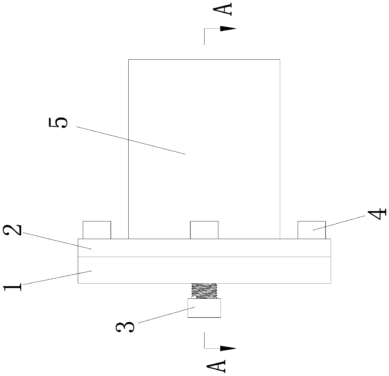
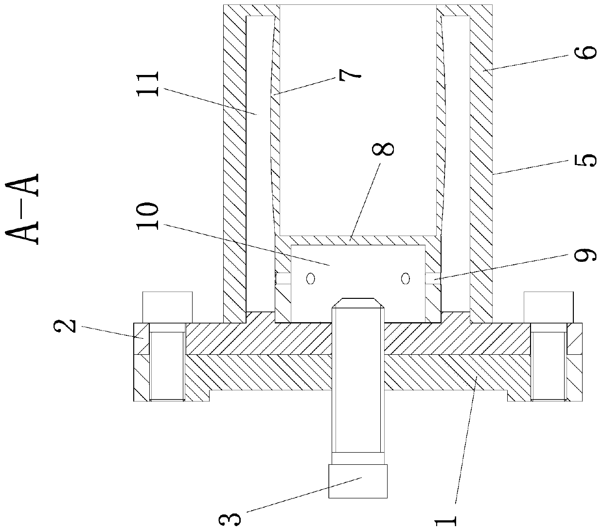
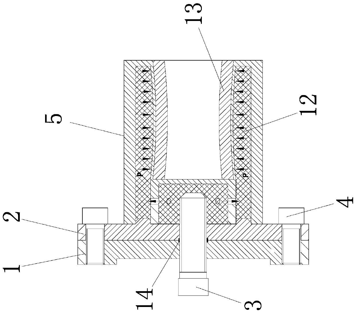
[0054] Such as Figure 1-3As shown, a liquid plastic fixture used for internal cutting of thin-walled sleeve parts. The liquid plastic fixture device is composed of a fixed chassis 1, a fixture seat 2, a clamping cylinder 5 and a pressure screw 3; the fixture The seat 2 is fixed on the fixed chassis 1 through the fixing screws 4, and the clamping cylinder 5 is fixedly arranged on the fixture seat 2. The clamping cylinder 5 is composed of the outer cylinder wall 6 and the inner cylinder wall 7, and the outer cylinder wall 6 and the inner cylinder An outer chamber 11 is formed between the walls 7, a partition 8 is provided at the inner bottom surface of the clamping cylinder 5, and an inner chamber 10 is formed by the partition 8, the side of the clamp seat 2 and the inner cylinder wall 7, and the inner chamber 10 is provided with Several through holes 9, the inner cavity 10...


PUM


Abstract

The invention discloses a liquid plastic clamp for inner cutting machining of thin-wall sleeve parts and a design method, and belongs to the general technical field of machinery. The clamp is composedof a fixed base plate, a clamp base, a clamping cylinder body and a pressurization screw rod which are connected with one another. The structure is novel, the design principle is clear, the liquid ofan inner cavity enters an outer cavity through rotation of the pressurization screw rod, the total liquid amount of the outer cavity is increased, deformation is generated by the non-equal-thicknesscylindrical wall structure of the inner side of the wall of the outer cavity, the deformation is large in two sides and small in the middle when the clamp is stressed, all parts of the outer wall of aworkpiece are subjected to the same load transmitted by the non-equal-thickness cylindrical wall, so that the deflection generated by cutting of a turning tool is reduced, the workpiece can be clamped, the clamp can keep high in position precision requirement, and the machining precision of the workpiece is improved.

Description

technical field [0001] The invention belongs to the general technical field of machinery, and relates to a liquid plastic fixture and a design method, in particular to a liquid plastic fixture and a design method for internal cutting processing of thin-walled sleeve parts. Background technique [0002] At present, whether it is the traditional manufacturing industry or the current flexible manufacturing system, a large number of parts need rough and fine machining, which determines the market demand for fixtures, and the processing of sleeve parts is very troublesome, especially thin-walled sleeve parts. . Due to the thin wall of the part, it is easy to deform during processing, so how to ensure the processing accuracy of the thin-walled sleeve part is the biggest problem faced. There are many improvements in the processing technology in the market to improve the processing quality, but this requires high technical requirements for the operator, and it is not easy to guaran...

Claims


Application Information

Patent Timeline
Patent Type & Authority Applications(China)
IPC IPC(8): B23Q3/06B23Q3/08G06F17/50
CPCB23Q3/062B23Q3/08G06F30/17G06F2119/06
Inventor 竺志大孙国荣张帆曾励戴敏杨坚寇海江
Owner YANGZHOU UNIV
Why Eureka
Try Eureka