Check patentability & draft patents in minutes with Patsnap Eureka AI!

Automatic clamping device

A technology of automatic clamping and clamping mechanism, applied in the direction of positioning device, clamping, support, etc., can solve the problems of the circular bearing seat of the boss is not accurately placed and clamped, not firm enough, and unfavorable production efficiency, etc. The tightening process is convenient and quick, the production qualification rate is improved, and the effect of avoiding the flying off of the workpiece

Pending Publication Date: 2019-08-09
FK BEARING GRP
View PDF0 Cites 0 Cited by
  • Summary
  • Abstract
  • Description
  • Claims
  • Application Information

AI Technical Summary

Problems solved by technology

[0003] The above-mentioned process of placing and clamping the circular bearing seat of the boss needs to be manually adjusted and positioned by the worker, and then the worker operates the wrench to manually tighten the clamp of the turning machine tool to place the circular bearing seat of the boss Clamping and fixing; the whole placement and clamping process is time-consuming and laborious, which is not conducive to further improving production efficiency. In addition, the labor intensity of workers is also relatively high
In addition, since the entire placement and clamping process relies on manual operation by workers, negligence is prone to occur during the manual operation, resulting in the inaccurate placement of the boss circular bearing seat or insufficient clamping. When processing the inner spherical surface hole, the circular bearing seat of the boss will rotate in the circumferential direction, and finally, the circular bearing seat of the boss produced and processed will be unqualified, which is not conducive to the further production qualification rate; in addition, if the circular bearing of the boss The seat is not clamped firmly, and there is a safety hazard of the workpiece flying off during the processing

Method used


Image

  • Automatic clamping device
  • Automatic clamping device
  • Automatic clamping device

Examples


Embodiment Construction

[0029] Preferred embodiments of the present invention will be described in detail below in conjunction with the accompanying drawings.

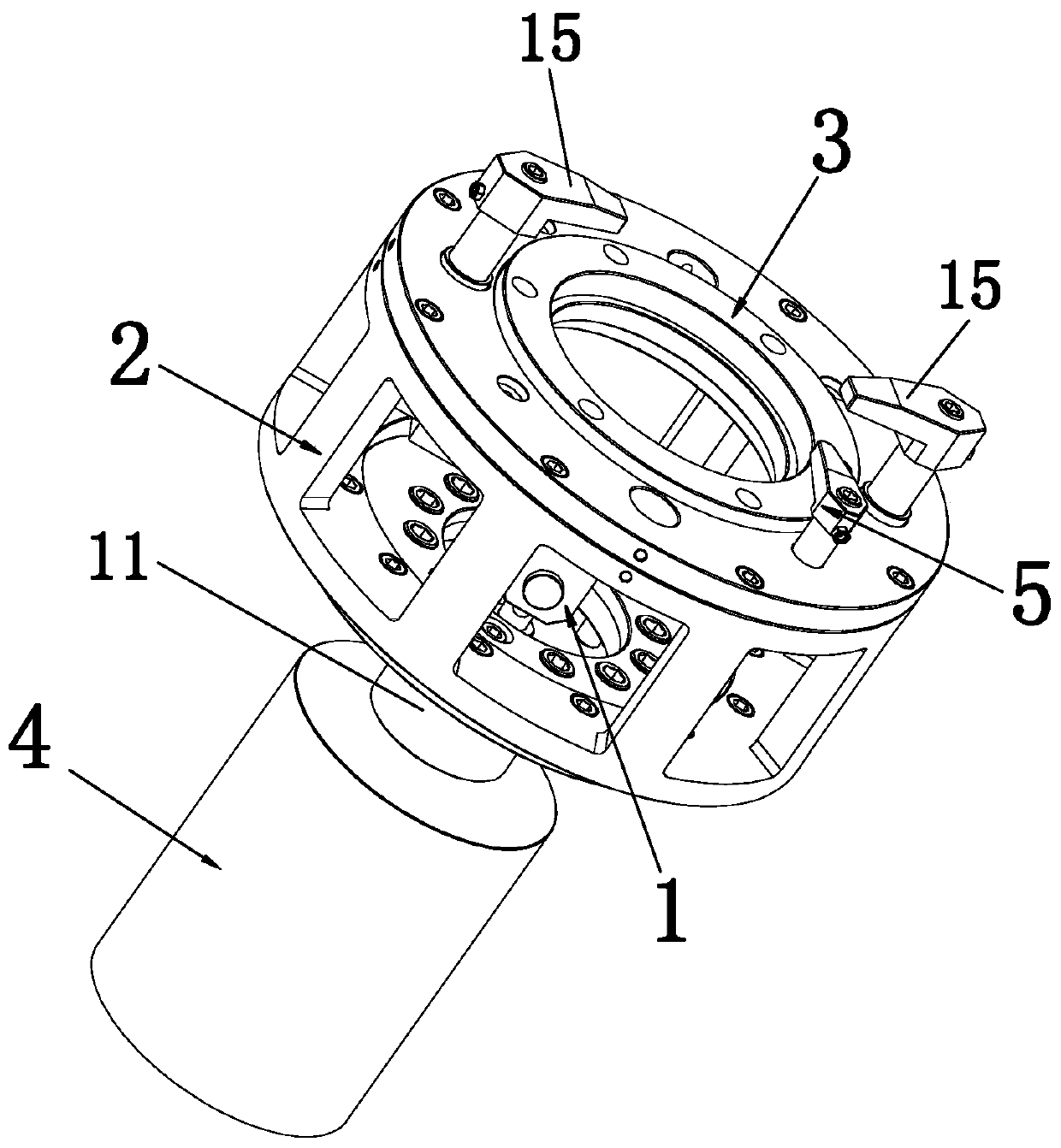
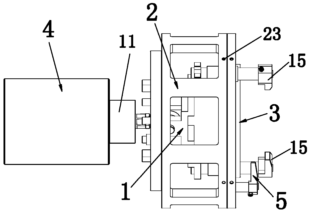
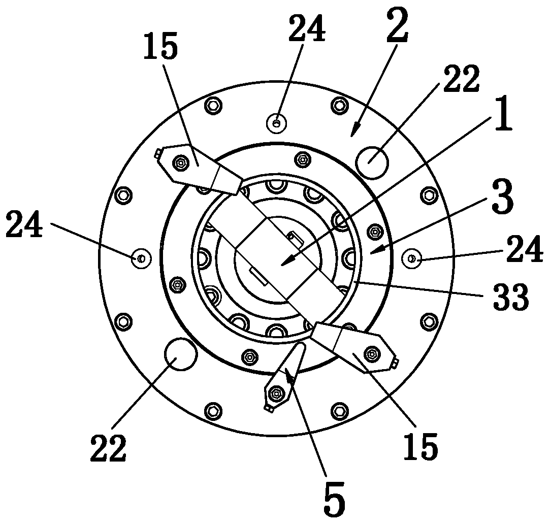
[0030] Such as Figure 1 to Figure 16 As shown, an automatic clamping device includes a cylinder 4, a base 2, a positioning plate 3, a clamping mechanism 1 and at least one limit mechanism 5, and the clamping mechanism 1 is installed on the base so that it can reciprocate left and right 2, the left end of the clamping mechanism 1 is connected to the piston rod of the cylinder 4, and the cylinder 4 can be replaced by a hydraulic cylinder. The middle part of the right end of the base 2 is fixedly equipped with a positioning disc 3, and the middle part of the positioning disc 3 is provided with a circular passage. hole 31, the left end of the circular through hole 31 is provided with a guide ring 32 protruding to the left, the inside of the circular through hole 31 is provided with a positioning boss 33, and the positioning boss 33 is used to po...


PUM


Abstract

The invention provides an automatic clamping device which comprises an air cylinder, a base, a positioning plate, a clamping mechanism and at least one limiting mechanism. The clamping mechanism is arranged on the base in a left-and-right reciprocating motion way; the left end of the clamping mechanism is connected with a piston rod of the air cylinder; the positioning plate is fixedly arranged inthe middle of the right end of the base; the at least one limiting mechanism is further arranged at the right end of the base; a lug boss circular bearing seat is positioned through the positioning plate; the air cylinder drives the clamping mechanism to move leftwards; a pressing claw at the right end of the clamping mechanism is matched with the positioning plate so as to automatically clamp the lug boss circular bearing seat; the arranged limiting mechanism is clamped to the outer side wall of the lug boss circular bearing seat; and during processing an inner spherical hole of the lug bosscircular bearing seat, the lug boss circular bearing seat can be prevented from rotating. By adopting the device provided by the invention, the lug boss circular bearing seat can be quickly, accurately and automatically clamped, the whole placing and clamping process is convenient and fast, the firmness in clamping is realized, the production efficiency can be effectively improved, and the production yield of the lug boss circular bearing seat can be effectively improved.

Description

technical field [0001] The invention relates to a clamping device, in particular to an automatic clamping device for fixing a boss circular bearing seat. Background technique [0002] Such as Figure 15 and Figure 16 As shown, it is a more commonly used boss circular bearing seat 6 in the field of bearings, and a circle of annular bosses 61 are arranged at the bottom of the boss circular bearing seat 6 . In the processing of the boss circular bearing seat, there is a process of turning the inner spherical surface hole. The existing operation method is manual loading and unloading to place and clamp the circular bearing seat of the boss on the fixture of the turning machine tool. During the placing and clamping process, the worker rotates the screw pair of the fixture by operating the wrench, so that the clamp on the fixture The pressure plate clamps the circular bearing seat of the boss. [0003] The above-mentioned process of placing and clamping the circular bearing se...

Claims


Application Information

Patent Timeline
Patent Type & Authority Applications(China)
IPC IPC(8): B23Q3/08
CPCB23Q3/08
Inventor 周有华陈志婷施天津伍海魂王宇凡
Owner FK BEARING GRP
Features
  • R&D
  • Intellectual Property
  • Life Sciences
  • Materials
  • Tech Scout
  • Unparalleled Data Quality
  • Higher Quality Content
  • 60% Fewer Hallucinations
Learn More