
Movable subway boarding and alighting flow-dividing device

A shunting device and mobile technology, which is applied in the field of movable subway passenger distributing device, can solve the problems of reducing the area of ​​the passage door for passengers getting on and off the subway, reducing the speed of getting on and off the subway, and affecting the speed of getting on and off the passengers, so as to protect passengers and devices, increase the rate of passengers getting on and off the subway, and improve efficiency

Pending Publication Date: 2019-08-09
SHANGHAI UNIV OF ENG SCI
View PDF1 Cites 2 Cited by
  • Summary
  • Abstract
  • Description
  • Claims
  • Application Information

AI Technical Summary

Problems solved by technology

[0002] At present, passengers on and off the subway generally adopt the strategy of "get off first, then get on". Passengers on and off the subway are crowded in the opposite direction at the entrance of the subway, which affects the speed of getting on and off the passengers and increases the probability of accidents. Generally, the management of passengers on the platform of the subway does not have other measures to limit and divert the flow of passengers except for the manual command of station attendants and other voice broadcasts. management, the possibility of a stampede or other accident undoubtedly increases
[0003] Chinese patent CN201410588400.9 discloses a passenger flow diversion device for passengers on and off the subway. A simple frame structure is erected at the entrance of the subway, and the subway door is divided into the left door and the right door to realize the diversion function, but the device can only The door is divided into two parts, which reduces the area of ​​the door for getting on and off passengers and reduces the speed of getting on and off the subway

Method used


Image

  • Movable subway boarding and alighting flow-dividing device
  • Movable subway boarding and alighting flow-dividing device
  • Movable subway boarding and alighting flow-dividing device

Examples


Embodiment Construction

[0028] The present invention will be described in detail below in conjunction with the accompanying drawings and specific embodiments. Apparently, the described embodiments are some, not all, embodiments of the present invention. Based on the embodiments of the present invention, all other embodiments obtained by persons of ordinary skill in the art without creative efforts shall fall within the protection scope of the present invention.

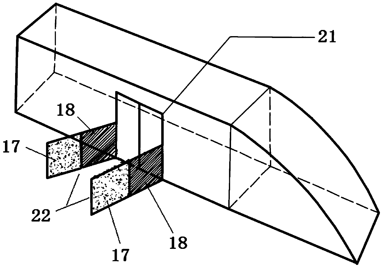
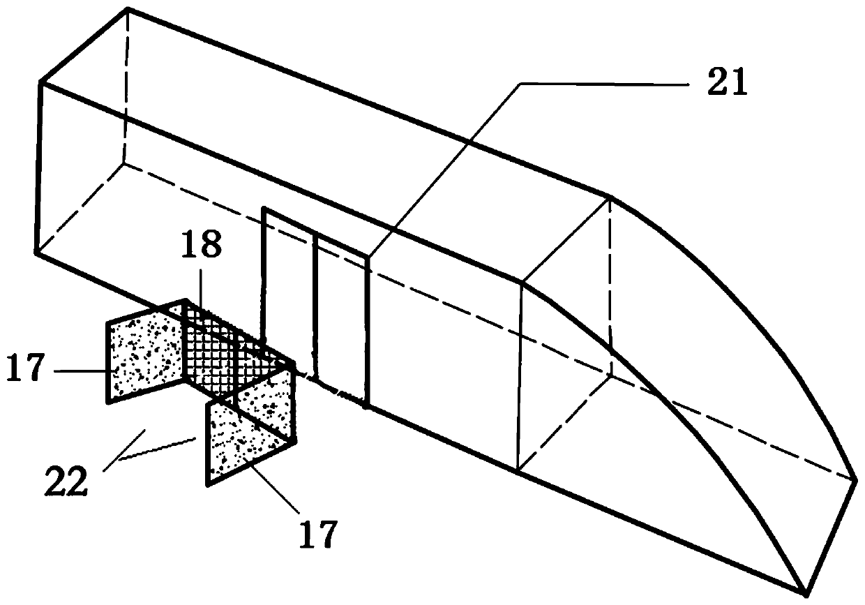
[0029] Such as figure 1 , figure 2 and Figure 4 As shown, the present invention provides a kind of movable subway passenger distributing device, and this device is arranged on the more crowded platform, and this device comprises the diversion door 22 that is symmetrically arranged on both sides of subway screen door 21, and diversion door 22 comprises fixed door 17. The revolving door 18 and the rotating shaft 12, the fixed door 17 and the revolving door 18 are rotatably connected through the rotating shaft 12 and two hinges 9, and the ...


PUM


Abstract

The invention relates to a movable subway boarding and alighting flow-dividing device. The movable subway boarding and alighting flow-dividing device comprises flow-dividing doors symmetrically arranged on the two sides of a subway shield door, each flow-dividing door comprises a fixed door, a rotatable door and a rotating shaft, each fixed door comprises a support, a control box, a third speed sensor and a power component, and each rotatable door comprises a first speed sensor, a second speed sensor, a balance torsional spring and a button component. Compared with the prior art, system safetyis improved through multiple protection of the button components and the speed sensors, the flow-dividing doors are fixed to the ground through the supports and thus are convenient to demount and move, door bodies have a straight-line-type alighting state and a right-angle-type boarding state, the flow-dividing function of boarding first and alighting second is achieved, through the function of standardizing passenger behavior, good taking consciousness is established, the condition of platform congestion is effectively relieved, and thus user experience is effectively enhanced.

Description

technical field [0001] The invention relates to a device for distributing passengers on and off the subway, in particular to a movable distributing device for distributing passengers on and off the subway. Background technique [0002] At present, passengers on and off the subway generally adopt the strategy of "get off first, then get on". Passengers on and off the subway are crowded in the opposite direction at the entrance of the subway, which affects the speed of getting on and off the passengers and increases the probability of accidents. Generally, the management of passengers on the platform of the subway does not have other measures to limit and divert the flow of passengers except for the manual command of station attendants and other voice broadcasts. Management, the possibility of a stampede or other accidents will undoubtedly increase. [0003] Chinese patent CN201410588400.9 discloses a passenger flow diversion device for passengers on and off the subway. A s...

Claims


Application Information

Patent Timeline
IPC IPC(8): B61B1/02B61L27/02
CPCB61B1/02B61L27/02
Inventor 刘滋曼黄远春刘志钢庄异凡
Owner SHANGHAI UNIV OF ENG SCI
Learn More