Zoom lens system having variable power element

a power element and zoom lens technology, applied in the field of zoom lens systems, can solve the problems of liquid crystal lenses with minimal adjustment through electrode modification, added cost, complexity, and size to the lens system, and affecting the design of lenses

Active Publication Date: 2007-02-22
MONUMENT PEAK VENTURES LLC
View PDF14 Cites 65 Cited by
  • Summary
  • Abstract
  • Description
  • Claims
  • Application Information

AI Technical Summary

Benefits of technology

[0050] The freedom to select the refractive indices of the liquids provides additional advantages when designing a zoom lens made in accordance with the present invention. As described above, inherent astigmatism can be controlled by shaping the faceplates rather than using plane parallel plates. The availability of a range of refractive indices allows the lens designer to determine several acceptable faceplate shape factors and thus have the freedom to select the most manufacturing friendly option. Additionally, the disclosed example embodiments demonstrate that utilizing a higher refractive index (N>1.6) for at least one of the liquids can produce desirable effects. For example, the primary lateral color in the middle zoom position of the second example embodiment is significantly reduced resulting in somewhat higher tangential MTF performance and less color fringing. Also, the shape of the rear faceplate in the second example embodiment can be allowed to move from a weighty biconcave lens shape (as shown in the first example embodiment) to a relatively simple meniscus lens shape (as shown in the second example embodiment).

Problems solved by technology

This movement adds cost, complexity, and size to the lens system.
As such, liquid crystal lenses have minimal adjustability through electrode modification and astigmatism is present in the lens system.
The zoom lenses described above have limitations.
While there is also a desired to reduce the number of moving groups in zoom lenses in order to reduce the overall size and complexity of the lenses, eliminating all the moving groups increases astigmatism in the lens system and sacrifices imaging quality.
Additionally, and at least in the case of the liquid lens systems described above, the various competing requirements for the liquids, for example, density, refractive index, freezing point, boiling point, conductivity, etc., make selection of the appropriate liquid very difficult to optimize.

Method used


Image

  • Zoom lens system having variable power element
  • Zoom lens system having variable power element
  • Zoom lens system having variable power element

Examples


Embodiment Construction

[0025] The present description will be directed in particular to elements forming part of, or cooperating more directly with, apparatus in accordance with the present invention. It is to be understood that elements not specifically shown or described may take various forms well known to those skilled in the art.

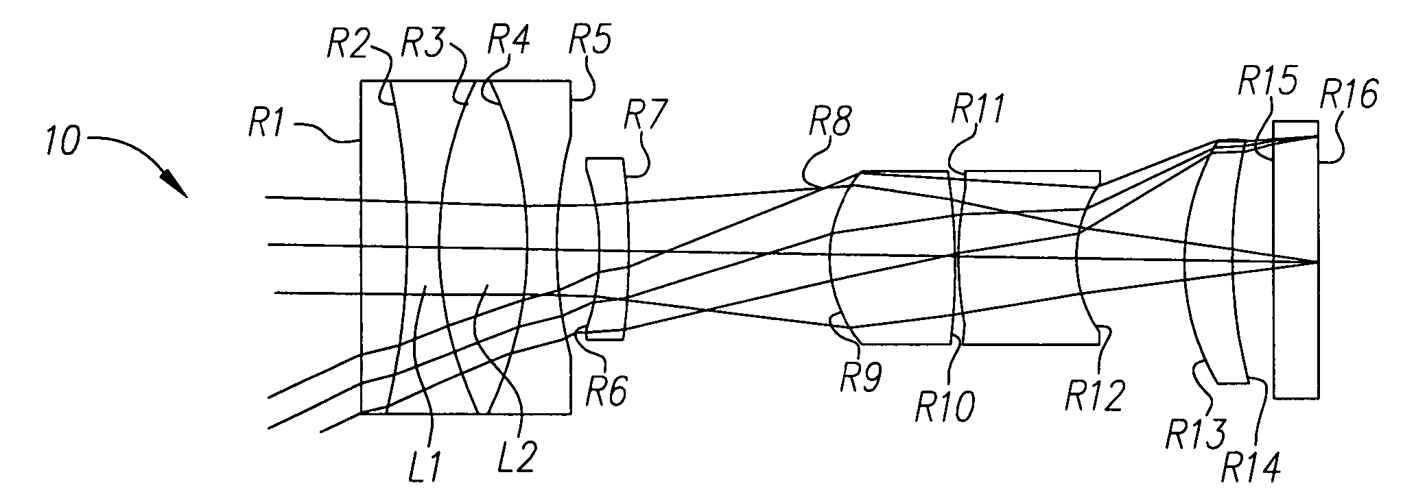
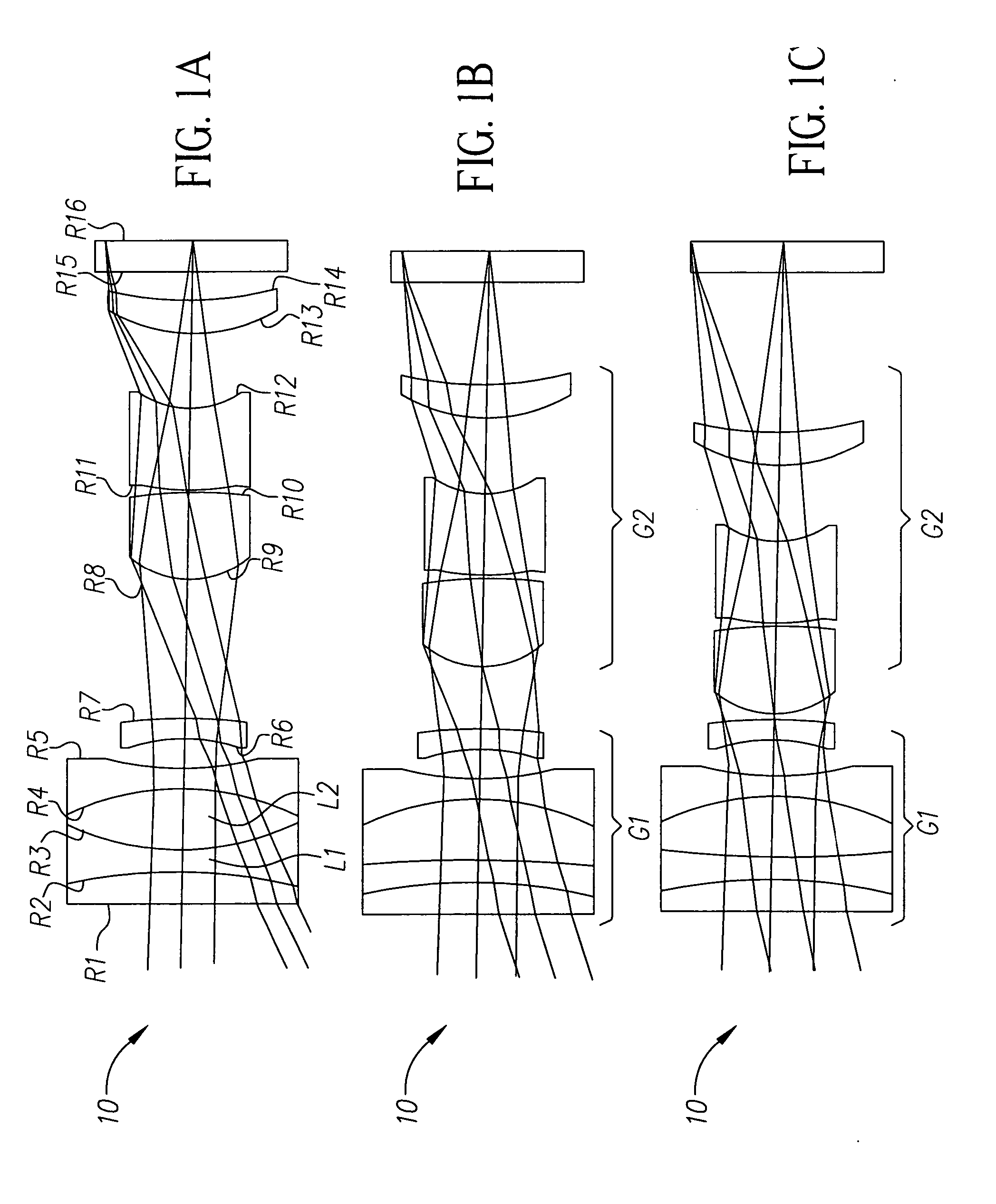
[0026] Referring generally to FIGS. 1A-8C, the present invention incorporates at least one variable optical power lens element in a variable focal length lens system 10, 20. When compared to lens systems that do not incorporate at least one variable optical power lens element, this results in the reduction of at least one moving group of the variable focal length lens system and reduces the overall length of the variable focal length lens system 10, 20. Also, the diameter of the most object side lens element of the system can be reduced depending on the specific application contemplated.

[0027] When a beam of light is obliquely incident on a refracting surface, astigmatism i...


PUM


Abstract

A multiple group variable focal length lens is provided. The lens has a first lens group including a variable power lens element and is positioned in a stationary manner along an optical axis. The lens also has a second lens group moveably positioned along the optical axis. The variable power lens element can be an electrically controllable liquid lens having a surface with a variable radius of curvature created by two liquids having distinct indices of refraction with one of the liquids having an index of refraction greater than 1.60. Alternatively or additionally, at least one of the liquids used in the liquid lens can include nanoscale particles.

Description

FIELD OF THE INVENTION [0001] This invention relates generally to lens design, and in particular to variable focal length lens systems having at least one variable power element. BACKGROUND OF THE INVENTION [0002] Conventional variable focal length lens systems, for example, zoom lens systems, typically include at least one group of lenses that is moved along an optical axis in order to change the focal length of the system resulting in variable magnification of an object at an image plane of the system. Zoom lens systems can include multiple moving groups or a combination of fixed lens groups and moving lens groups. These types of lens systems have various design forms with each design form having its own set of strengths in terms of size, performance, cost, mechanical complexity, etc. Conventional variable focal length lens systems mechanically move lens groups to achieve variable focal length. This movement adds cost, complexity, and size to the lens system. In consumer camera ap...

Claims


Application Information

Patent Timeline
Patent Type & Authority Applications(United States)
IPC IPC(8): G02B15/14
CPCG02B3/14G02B15/177G02B26/005G02B15/1425
Inventor GOOSEY, WILLIAM T. JR.BORDER, JOHN N.SANDFORD, DAVID W.
Owner MONUMENT PEAK VENTURES LLC
Why Eureka
Try Eureka