Light dimmer for LED and incandescent lamps

Inactive Publication Date: 2005-08-04
RADIANT POWER
View PDF20 Cites 61 Cited by
  • Summary
  • Abstract
  • Description
  • Claims
  • Application Information

AI Technical Summary

Benefits of technology

[0036] An advantage of the present invention is that two different kinds of illumination devices—LEDs and incandescent lamps—can be controlled so that their output intensity levels L will substantially track each other. In this case, “substantially” means from the subjective viewpoint of a human observer—in objective terms, within plus or minus only a few percent (e.g., +/−5%).
[0037] Another advantage of the present invention is that not only can LEDs and incandescent lamps be mixed, on the same power bus,

Problems solved by technology

But LEDs are not typically powered from a true current source.
Generally speaking, powering LEDs directly from a voltage source is not such a good idea.
And, of course, series resistors represent power losses.
Since techniques for controlling illumination are different for each, this creates some challenges, and in “next generation” cockpits (aircraft designed less than 10 years ago)

Method used


Image

  • Light dimmer for LED and incandescent lamps
  • Light dimmer for LED and incandescent lamps
  • Light dimmer for LED and incandescent lamps

Examples


example 1

ination (L=0.5)

[0062] Supply voltage (VMAX) is 5 V.

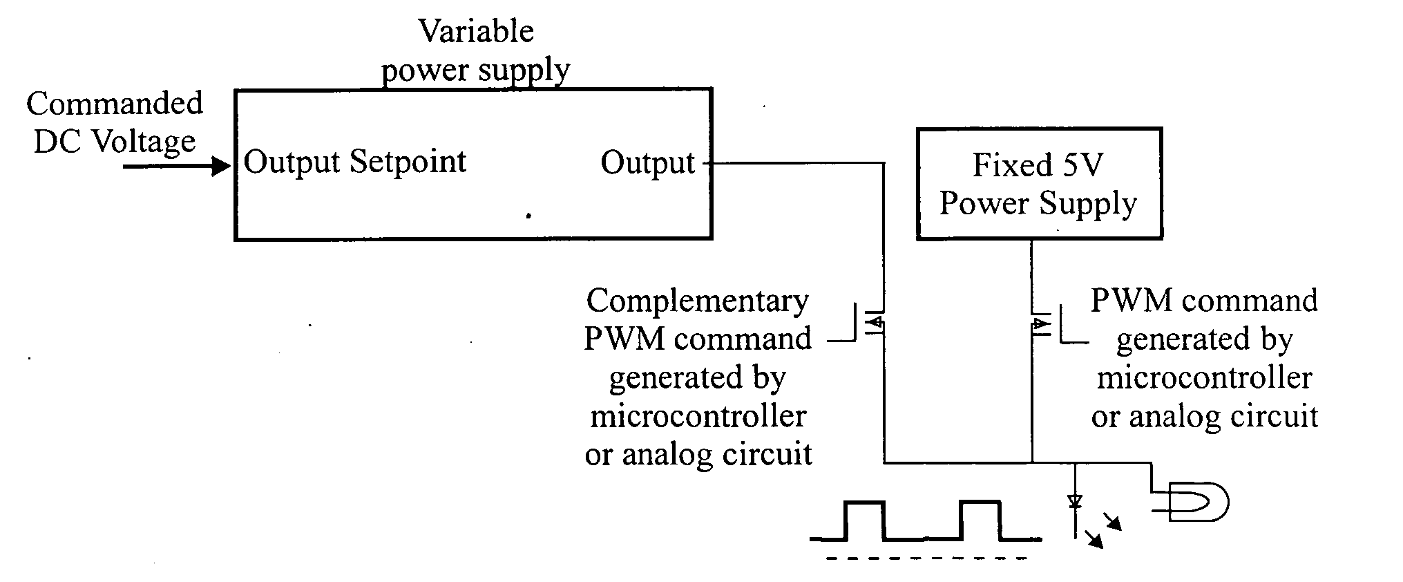
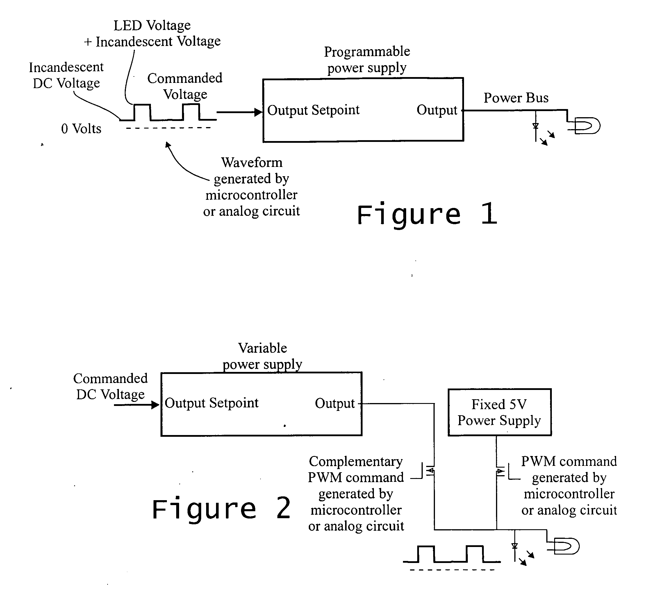
[0063] The signal powering the LEDs and incandescent lamps has two components, a pulse-width modulated (PWM) component and a DC component.

[0064] LED: D=0.5 (50%)

[0065] The 5V signal (VMAX) is PWM modulated at D=50%.

[0066] Incandescent: 0.5=(VRMS15⁢ ⁢V)3.4⁢ ⁢or⁢ ⁢0.816=(VRMS15⁢ ⁢V)⁢ ⁢or⁢ ⁢4.078=VRMS1

[0067] Therefore, 4.078 Vrms is needed for the incandescent lamp to light at 50%.

[0068] The incandescent lamp will respond to the total RMS voltage. This is also called a quadrature power solution because the applied signal is composed of two voltages at different frequencies—DC and the PWM signal. The task is thus to compute the DC voltage, present at a duty cycle of (1-D) that will produce the desired RMS voltage at the incandescent lamp.

[0069] RMS voltage of a Waveform at Vmax for D and V2 for 1-D: VRMS=∫01⁢v2⁡(t)⁢ ⁢ⅆt=∫0D⁢Vmax2⁡(t)⁢ ⁢ⅆt+∫D1⁢V22⁡(t)⁢ ⁢ⅆt=Vmax2⁡(D)+V22⁡(1-D)solving⁢ ⁢for⁢ ⁢V2:V2=(VRMS)2-Vmax2⁡(D)(1-D)⁢(principal...

example 2

ination (L=0.9)

[0072] LED: D=0.9 (90%)

[0073] Incandescent: 0.9=(VRMS15⁢ ⁢V)3.4⁢ ⁢or⁢ ⁢0.969=(VRMS15⁢ ⁢V)⁢ ⁢or⁢ ⁢4.847=VRMS1

[0074] VRMS=4.847

[0075] D=0.9

[0076] VMAX=5

[0077] V2=3.159

example 3

ination (L=0.10)

[0078] LED: D=0.1(10%)

[0079] Incandescent: 0.1=(VRMS15⁢ ⁢V)3.4⁢ ⁢or⁢ ⁢0.508=(VRMS15⁢ ⁢V)⁢ ⁢or⁢ ⁢2.540=VRMS1

[0080] VRMS=2.54

[0081] D=0.1

[0082] VMAX=5

[0083] V2=2.096 V


PUM


Abstract

The light output intensity of incandescent lamps and LEDs connected to a common lamp power bus are controlled using a composite waveform having two power components: a pulse-width modulated (PWM) component and a direct current DC component. The DC component is maintained below the turn-on voltage for the LEDs. The PWM component controls the light intensity of the LEDs; and the DC component is calculated as a quadrature power series, taking into account that the PWM component contributes to the light intensity of the incandescent lamps. The frequency and slew rate of the PWM component are selected to minimize EMI. A small steady state power component is provided to keep the LEDs slightly turned on to minimize EMI.

Description

TECHNICAL FIELD OF THE INVENTION [0001] The invention relates to light dimmers and, more particularly, to controlling the intensity of (dimming) incandescent lamps and light-emitting diodes (LEDs). BACKGROUND OF THE INVENTION [0002] Incandescent lamps (or bulbs, or light bulbs) operate differently than light emitting diodes (LEDs). (LEDs are also referred to as “LED lamps”.) Basically, incandescent lamps are voltage driven devices, and LEDs are current driven devices. They therefore require different techniques for controlling (e.g., dimming) the intensity of their respective light outputs. [0003] For an incandescent lamp the amount of light produced is more-or-less proportional to the cube of the applied voltage—more specifically, it is proportional to the 3.4th power of the ratio of the RMS (Root-Mean-Square) voltages. (The RMS voltage is the square root of the mean value of the square of the instantaneous voltage.) That means, if the RMS voltage is reduced by one half (½), the li...

Claims


Application Information

Patent Timeline
IPC IPC(8): H05B35/00H05B39/04
CPCH05B33/0818H05B39/047H05B35/00Y02B20/00H05B45/325
Inventor ELLIOTT, STEPHEN
Owner RADIANT POWER
Why Eureka
Try Eureka