Power Module

a power module and power supply technology, applied in the field of power modules, can solve the problems of power loss, power loss, and tendency to detach or rupture, and achieve the effect of small dimensions and low weigh

Active Publication Date: 2016-05-12
AT & S AUSTRIA TECH & SYSTTECHN AG
View PDF1 Cites 54 Cited by
  • Summary
  • Abstract
  • Description
  • Claims
  • Application Information

AI Technical Summary

Benefits of technology

[0011]Power modules according to the invention can process high currents and powers, wherein they are characterised by low weight and small dimensions. An important field of use is constituted for example by voltage converters in electric vehicles, specifically both in hybrid vehicles and in pure electric vehicles.
[0012]It is advantageous when at least the metal inner layers of the heat dissipation plates consist of copper, since copper is a proven material in view of the formation of conductive tracks and in view of its thermal conductivity.

Problems solved by technology

In order to meet the electrical and thermal requirements, the guidance of the terminal lines must be complex, wherein for example thick aluminium wires are used for the connection of gate and source contacts, arranged at the top, of IGBTs, however these wires, on account of their high coefficient of thermal expansion, tend to detach or rupture on account of what are known as “heel cracks” at bends.
It has been demonstrated, however, that faults occur with relatively long periods of operation and are to be attributed to cycles of the performance and thermal stress and resultant different expansions of the components and cracks and material fatigue and manifest themselves for example in a detachment of the aluminium wires or in breaks of the chip or substrate.
The previously preferably used embeddings of power semiconductors are also characterised by a high self inductance of the wire connections, which leads to power losses and high heating, and by the use of costly substrates for the electrical insulation and heat transfer.
Although double-sided cooling is applied here, the problem of high-current lines to the power terminals (source of the IGBTs, anodes of the diodes), primarily in view of the self-inductances, remains unsolved.

Method used


Image

  • Power Module
  • Power Module
  • Power Module

Examples


Embodiment Construction

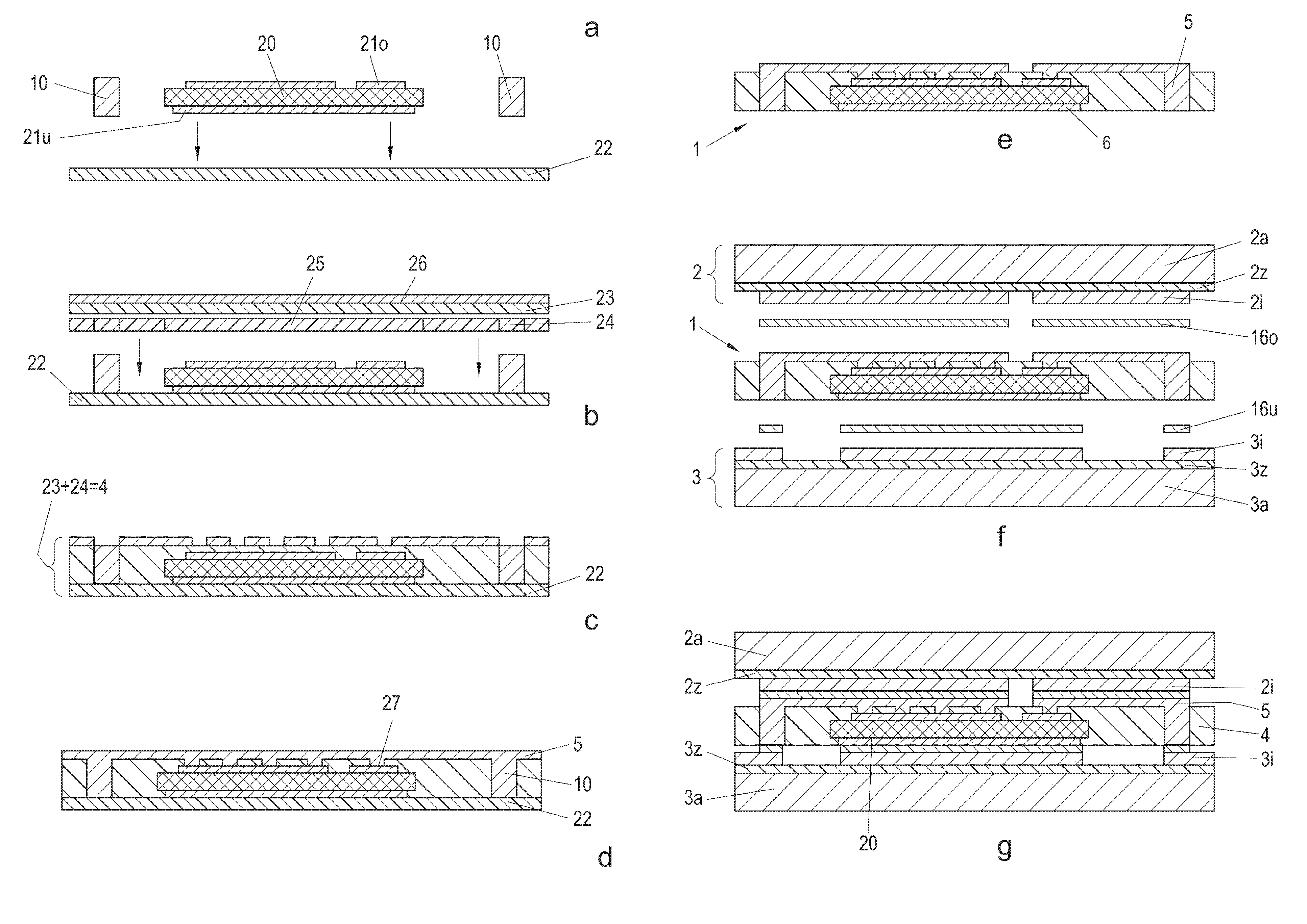
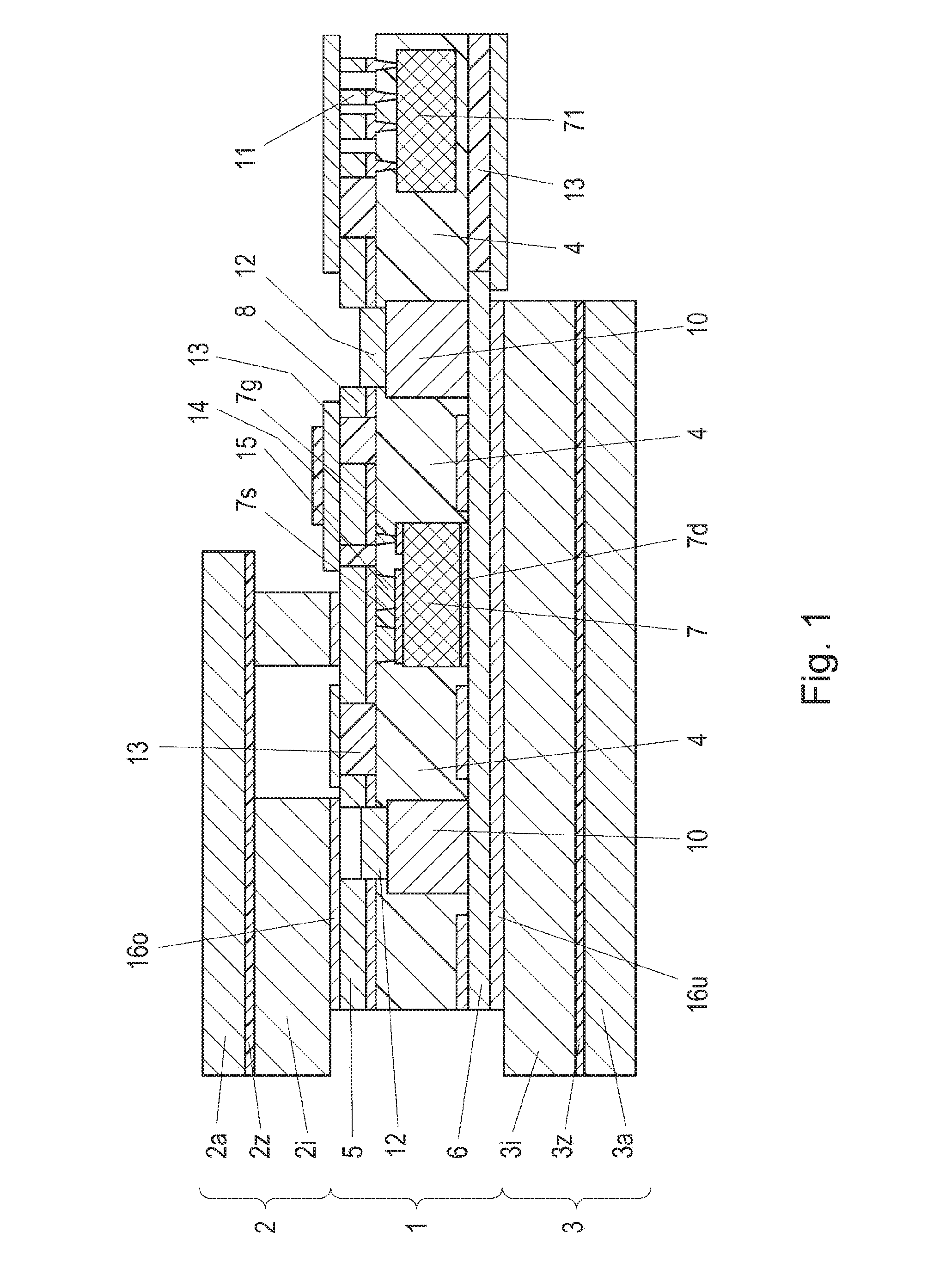
[0026]FIG. 1 shows, partly schematically, a first embodiment of a power module according to the invention, which has a printed circuit board core 1 arranged between two heat dissipation plates 2 and 3. The printed circuit board core 1 consists, as is the case with a conventional two-sided printed circuit board, of an insulating layer 4, for example a prepreg, which is conventional in printed circuit board construction and which on both sides has a conductor layer, specifically a copper layer. Here, the upper conductor layer 5 is structured so as to form conductive tracks 8, however the lower conductor layer 6 does not necessarily have to be structured in the present example. In the present case an IGBT chip 7, an IGBT driver 71, and two copper inlays 10 are embedded in the insulating layer 4.

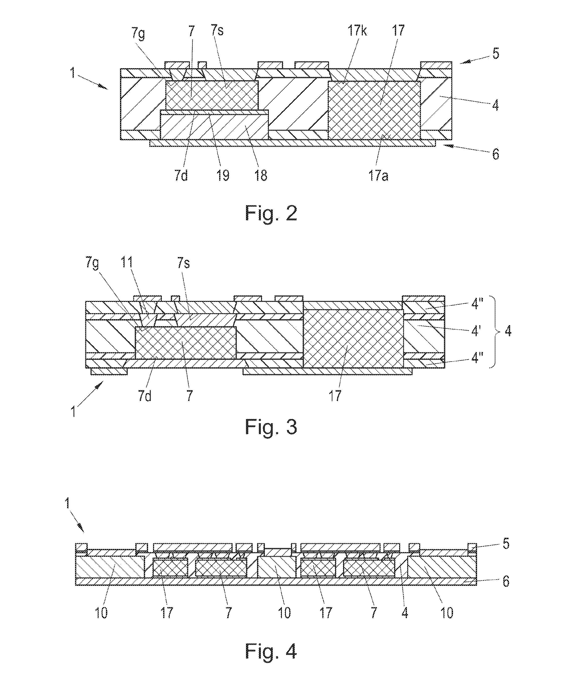
[0027]The IGBT chip 7 has three electrode terminals, specifically a lower drain terminal 7d, an upper source terminal 7s, and an upper gate terminal 7g. The terminals of the IGBT chip 7 are adva...


PUM


Abstract

A power module, having a printed circuit board core, which contains at least one electronic power component embedded in an insulating layer, the core being arranged between two heat dissipation plates wherein each heat dissipation plate has a metal outer layer and a metal inner layer electrically separated from said metal outer layer by a thermally conductive, electrically insulating intermediate layer, and electrode terminals of the at least one power component are guided out from the core via terminal lines, wherein the printed circuit board core on both sides of the insulating layer has a conductor layer, at least one conductor layer is structured at least in portions, and each conductor layer is connected at least in portions via a conductive, metal intermediate layer to a metal inner layer of the heat dissipation plate, contacts run from the structured conductor layer to the electrode terminals of the at least one power component, and at least one power terminal of the at least one power component is connected via a contact, a portion of a structured conductor layer, and the conductive, metal intermediate layer to at least one portion of the metal inner layer of the heat dissipation plate, which forms part of the terminal line to the electrode terminal.

Description

BACKGROUND OF THE INVENTION[0001]1. Subject of the Invention[0002]The invention relates to a power module, having a printed circuit board core which contains at least one electronic power component embedded in an insulating layer, the core being arranged between two heat dissipation plates, wherein each heat dissipation plate has a metal outer layer and a metal inner layer electrically separated from said metal outer layer by a thermally conductive, electrically insulating intermediate layer, and electrode terminals of the at least one power component are guided out from the core via terminal lines.[0003]2. Prior Art[0004]In the case of power modules, which for example include IGBTs together with freewheeling diodes and which are intended to process high currents and voltages, which for example in the automotive field in the case of DC / AC converters in the case of electric drives lie in the region of 500 volts and 200 amperes and also thereabove, there is a need to keep the thermal ...

Claims


Application Information

Patent Timeline
Patent Type & Authority Applications(United States)
IPC IPC(8): H01L23/498H01L23/367H01L23/31
CPCH01L23/49838H01L23/367H01L23/3121H01L23/13H01L23/3107H01L23/49833H01L23/5389H05K1/182H05K7/209H01L23/36H01L23/3735H01L23/5385H01L2924/0002H01L2224/18H01L24/19H01L24/24H01L24/82H01L2224/82005H01L2224/04105H01L2224/06181H01L2224/24137H01L2224/32245H01L2224/73267H01L2224/92244H01L2924/13055H01L2924/13091H01L2224/0603H01L2224/2518H01L2224/82039H01L2924/00
Inventor STAHR, JOHANNESZLUC, ANDREASGROBER, GERNOTSCHWARTZ, TIMO
Owner AT & S AUSTRIA TECH & SYSTTECHN AG
Why Eureka
Try Eureka