A pipe gallery anti-seismic energy buffering support structure

A support structure and pipe gallery technology, applied in the direction of pipe supports, springs/shock absorbers, pipes/pipe joints/pipe fittings, etc., can solve the problems of pipe gallery transmission vibration and poor seismic performance, so as to reduce the impact and strengthen the buffering effect , the effect of reducing the impact

Active Publication Date: 2020-06-30
JINAN MUNICIPAL ENG DESIGN & RES INSITITUTE GRP
View PDF10 Cites 0 Cited by
  • Summary
  • Abstract
  • Description
  • Claims
  • Application Information

AI Technical Summary

Problems solved by technology

[0003] The technical problem to be solved by the present invention is to solve the problem of the pipe gallery conducting vibration and poor seismic performance in the prior art, and to propose a pipe gallery anti-seismic energy buffering support structure, which can improve the anti-seismic energy buffering performance of the pipe gallery

Method used


Image

  • A pipe gallery anti-seismic energy buffering support structure
  • A pipe gallery anti-seismic energy buffering support structure
  • A pipe gallery anti-seismic energy buffering support structure

Examples


Embodiment 1

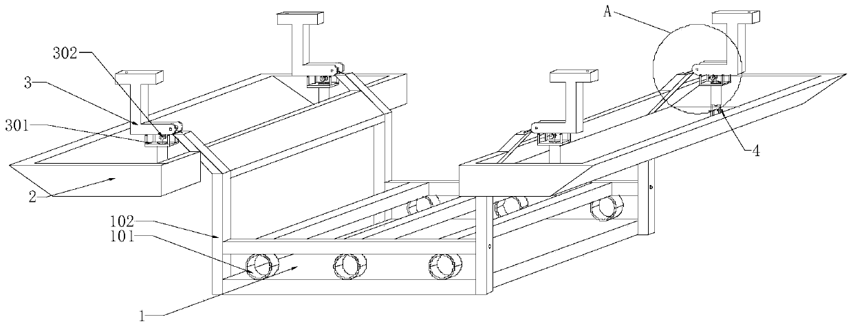
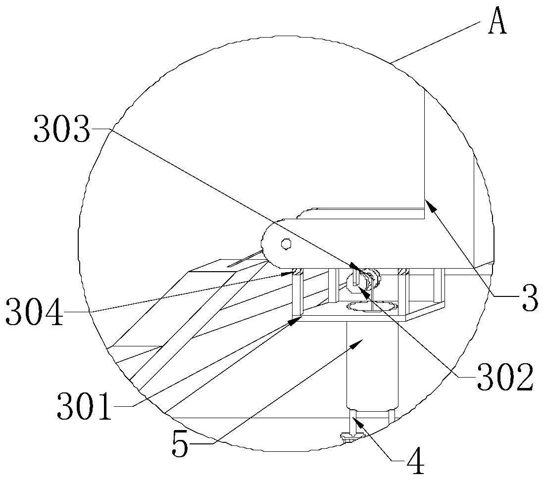
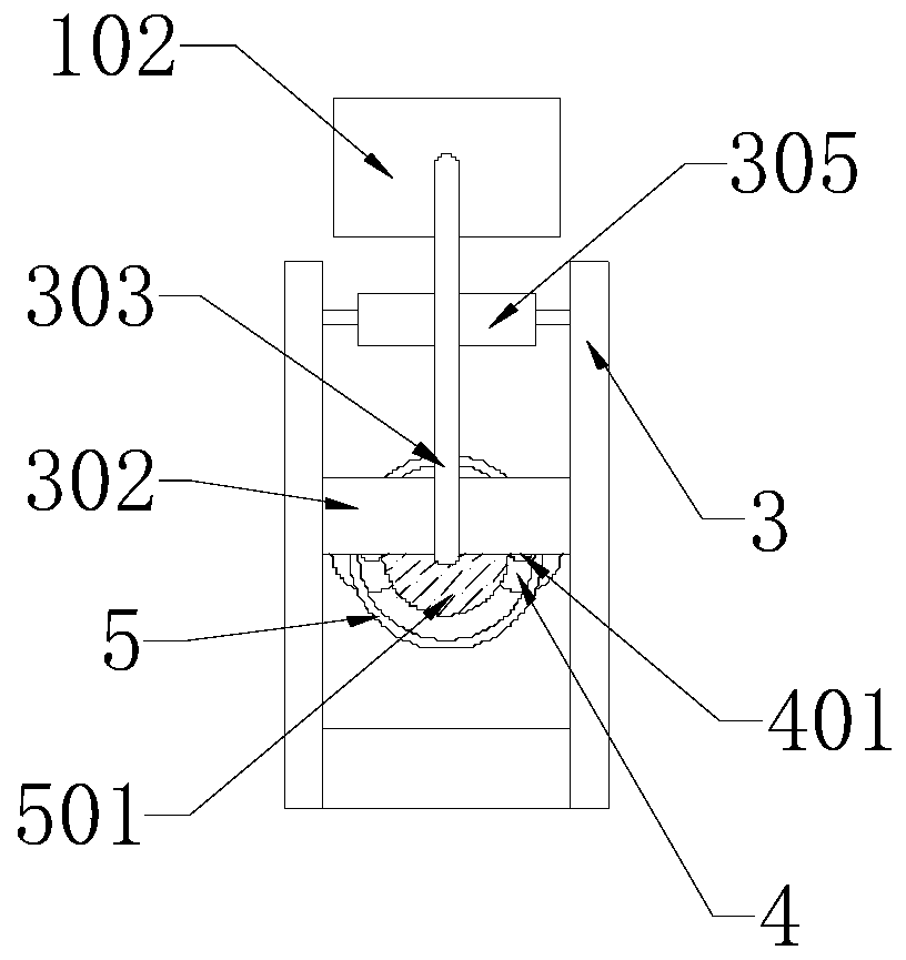
[0033] The present invention provides an anti-seismic energy buffering support structure for a pipe gallery, which includes a supporting plate 1, a hoop 101, a side column 102, a box-shaped body 2, a top frame 3, a connecting platform 301, a second pulley 302, a traction cable 303, and a spring block 304, the first pulley 305, the force guide branch 4, the connecting ball 401, the support cylinder 5 and the buffer sheet 501, the top surface of the support plate 1 is fixedly connected with a plurality of hoops 101, and the four-corner top surface of the support plate 1 is fixedly connected with the side columns 102 , the side column 102 away from the supporting plate 1 side is fixedly connected with a box-shaped body 2, in this embodiment the boxed body 2 is used to hold pure water, the top of the side column 102 is fixedly connected to the top frame 3, and the top frame 3 is connected to The platforms 301 are connected by a spring block 304, the top frame 3 is movably provided ...

Embodiment 2

[0041] The difference between embodiment 2 and embodiment 1 is that in embodiment 2, the box-shaped body 2 contains a non-volatile solvent, such as brine.

Embodiment 3

[0043] Embodiment 3 discloses a method for constructing a pipe gallery anti-seismic energy buffering support structure, including the following steps:

[0044] Fix the top frame 3 on the top of the pipe gallery, and pass the pipeline through the hoop 101;

[0045] The traction cable 303 fixed on the top surface of the side column 102 goes around the first pulley 305 and the second pulley 302, and the buffer piece 501 is placed on the end section of the traction cable 303, and the connecting ball 401 is stuck between the buffer pieces 501 at the same time ;

[0046] Fix the buffer piece 501 to the end section of the traction cable 303, and at the same time pass the connecting table 301 through the buffer piece 501, so that the connecting ball 401 and the buffer piece 501 are placed in the support cylinder 5;

[0047] The top surface of the spring block 304 is fixed on the bottom surface of the top frame 3;

[0048] Liquid is injected into the box-shaped body 2 .

[0049] Whe...


PUM


Abstract

The invention discloses a pipe rack anti-vibration energy buffering support structure. Top frames, first pulleys, second pulleys, traction cables, buffering sheets and connecting balls are included. Each top frame is movably provided with the corresponding first pulley and the corresponding second pulley, wherein the corresponding traction cable is wound around the peripheries of the first pulleyand the second pulley. The bottom end of each top frame is elastically connected with a connecting table, wherein the lower portion of the connecting table is connected with a support barrel. The traction cables are connected with the buffering sheets, the buffering sheets are arranged in the support barrels, the connecting balls are arranged between the buffering sheets and the support barrels, the edges of the buffering sheets can abut against the connecting balls, and a force guiding branch is arranged below each support barrel. A support plate, edge columns and box-shaped bodies are further included. The support plate is connected with the edge columns, and the corresponding box-shaped body is arranged on one side of each edge column. The box-shaped bodies are used for containing liquid. The start ends of the traction cables are connected with the edge columns, and the force guiding branches are arranged in the box-shaped bodies. By means of the pipe rack anti-vibration energy buffering support structure, the pipe rack anti-vibration energy buffering performance can be greatly improved.

Description

technical field [0001] The invention belongs to the field of pipe gallery support structures, and in particular relates to a pipe gallery anti-seismic energy buffering support structure. Background technique [0002] Pipe gallery, that is, the corridor of pipelines. Many pipes are gathered together and arranged at a low level along the pipe gallery. Generally, they are supported by brackets to form a similar appearance to the corridor. There are also a few pipe galleries located underground, but the existing pipe gallery is earthquake-resistant. The strength is often not high. Once an earthquake disaster occurs or a large impact occurs, the bracket will be separated from the ceiling of the pipe gallery, which will cause the pipe to fall without support, so that the pipe cannot be kept on the same plane, which will affect the overall life of the pipe gallery. Based on the above description, the inventor believes that , most of the existing pipe gallery supports are rigidly co...

Claims


Application Information

Patent Timeline
Patent Type & Authority Patents(China)
IPC IPC(8): F16L3/227F16F15/023F16F15/04
CPCF16F15/023F16F15/04F16L3/227
Inventor 杨帆张宁宁刘传佩王胜华葛丰源
Owner JINAN MUNICIPAL ENG DESIGN & RES INSITITUTE GRP
Why Eureka
Try Eureka