Double-catalyst coating louver-type heat collecting wall and using method thereof

A dual-catalyst, louver-type technology, applied in the field of double-catalyst-coated louver-type heat collecting walls, can solve the problems of single function of heat collecting walls and inability to adapt to various working modes, so as to increase and reduce indoor heat load Effect

Pending Publication Date: 2019-08-09
HEFEI INST FOR PUBLIC SAFETY RES TSINGHUA UNIV
View PDF1 Cites 8 Cited by
  • Summary
  • Abstract
  • Description
  • Claims
  • Application Information

AI Technical Summary

Problems solved by technology

[0007] One of the technical problems to be solved by the present invention is: how to solve the problem of single function of the existing heat collecting wall
[0008] The second technical problem to be solved by the present invention is: how to solve the problem that the existing heat collecting wall has a single function and cannot adapt to various working modes

Method used


Image

  • Double-catalyst coating louver-type heat collecting wall and using method thereof
  • Double-catalyst coating louver-type heat collecting wall and using method thereof
  • Double-catalyst coating louver-type heat collecting wall and using method thereof

Examples


Embodiment 1

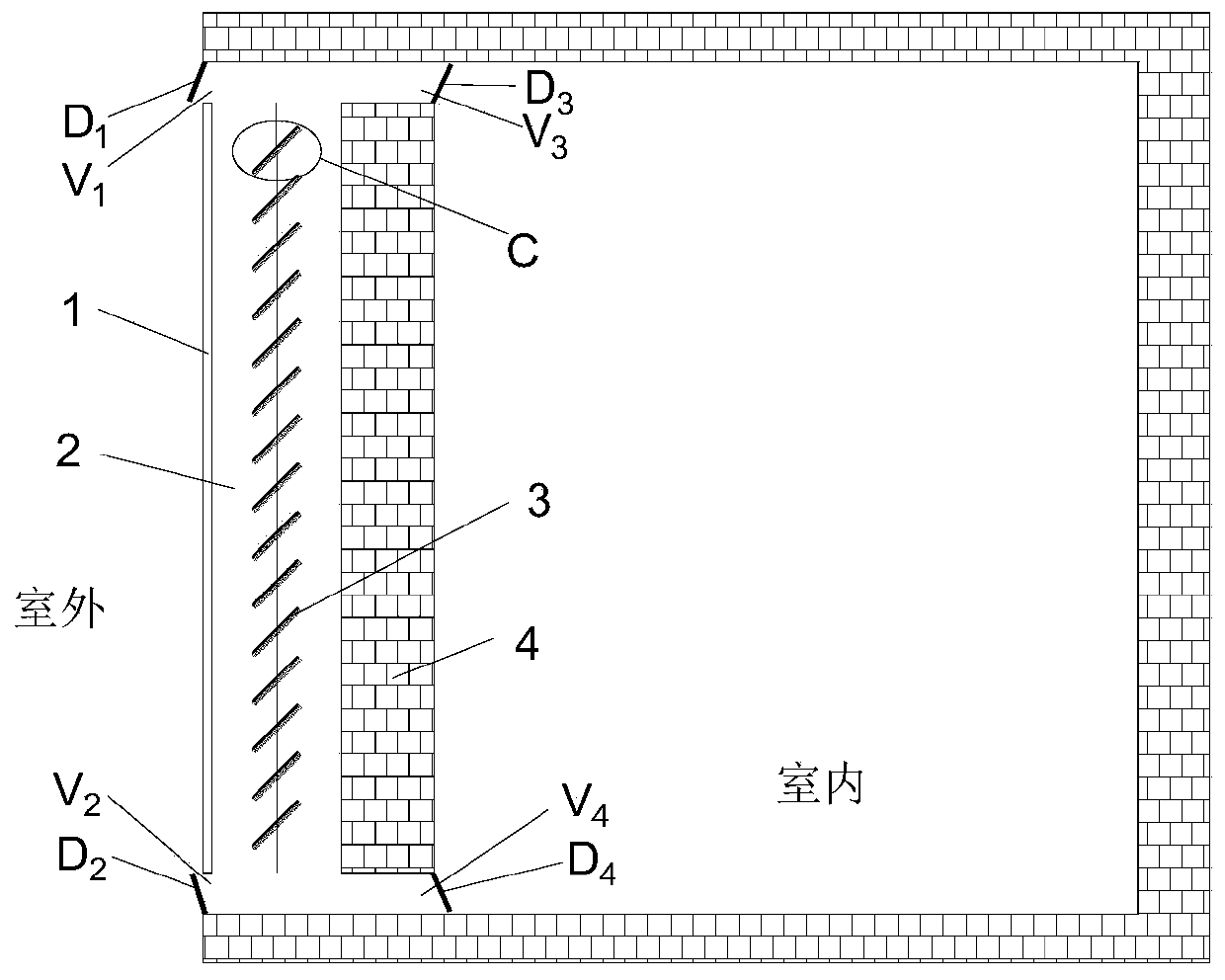
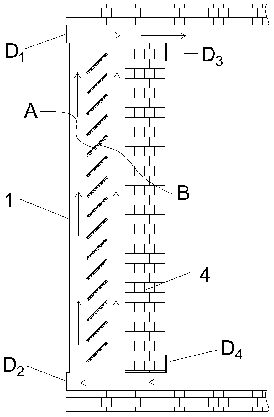
[0033] Such as figure 1 , 2 As shown, the double-catalyst-coated louver-type heat collecting wall in this embodiment includes light-transmitting glass 1, venetian blind 3, and heat-collecting heat-storage wall 4 arranged in parallel in sequence; It is the air channel 2, and the upper and lower ends of the light-transmitting glass 1 are provided with a first outdoor vent V1, a second outdoor vent V2, and a first outdoor vent V1 and a second outdoor vent V2 to open and close. The outdoor baffle D1 and the second outdoor baffle D2; the upper and lower ends of the heat collecting and storage wall 4 are provided with a first indoor vent V3 and a second indoor vent V4, and realize the first indoor vent V3 and the second indoor ventilation The first indoor baffle D3 and the second indoor baffle D4 that open and close the port V4, the first outdoor vent V1 and the first indoor vent V3 are on the same horizontal line, the second outdoor vent V2 and the second indoor vent V4 is on the...

Embodiment 2

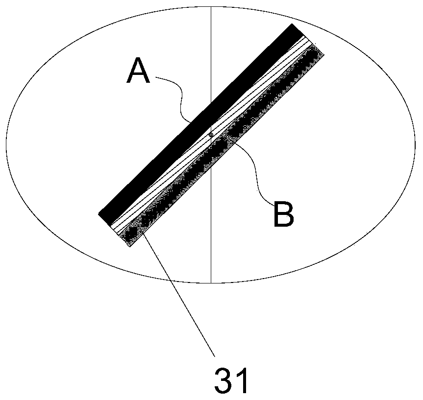
[0038] In this embodiment, on the basis of Embodiment 1, the materials of the thermal catalytic layer are noble metal catalysts (Pt, Au, Rh, Pd), transition metal catalysts (CuO, MnOx, CeO 2 ) in one or more combinations, select MnOx-CeO2, MnOx-CeO in the present embodiment 2 It is black in color, and its absorptivity in the sunlight band is 0.94. The thermal catalytic layer has good heat collection efficiency, and it will be stimulated to oxidize and degrade organic pollutants at a certain temperature.

[0039] The photocatalyst layer is made of one or more combinations of titanium dioxide, zinc oxide, tin oxide, zirconium dioxide and cadmium sulfide. Among them, the photocatalyst material is preferably white titanium dioxide, because of its strong oxidizing ability, stable and non-toxic chemical properties, it has become the most popular nano photocatalyst material in the world, TiO 2 It can degrade organic pollutants under the excitation of ultraviolet light, and the photo...


PUM


Abstract

The invention discloses a double-catalyst coating louver-type heat collecting wall, and also discloses a using method thereof. The double-catalyst coating louver-type heat collecting wall comprises transparent glass, a louver curtain and heat collecting and storage walls, wherein an air flow channel is arranged between the transparent glass and the heat collecting and storage walls; the upper endand the lower end of the transparent glass are provided with a vent and a baffle for achieving opening and closing of the vent; a vent and a baffle plate of the vent are arranged at the upper end andthe lower end of the heat collecting and storage walls; the louver curtain comprises a plurality of blades capable of rotating circumferentially; and one surface of each blade is coated with a hot catalyst layer, and the other surface of each blade is coated with a photocatalyst layer. The double-catalyst coating louver-type heat collecting wall has the beneficial effects that heat collecting andpurification in the daytime in winter and heat preservation at night can be achieved; heat dissipation and purification in the daytime in summer and radiation refrigeration at night can be achieved; the problem of single function of the traditional heat collecting wall is effectively solved; solar energy is effectively utilized to purify indoor air and guarantee the health of a human body; and thetriple functions of solar energy purification, heating and refrigeration are provided.

Description

technical field [0001] The invention relates to a heat collecting wall and its use method, in particular to a double-catalyst-coated louver-type heat collection wall and its use method. Background technique [0002] The heat collecting wall is also called the Trombe wall, and the English name is Trombe wall, referred to as the heat collecting wall. It is the most typical component of the heat collecting and heat storage wall passive solar house. [0003] The heat collecting wall is to use sunlight to shine on the dark heat storage wall with a glass cover outside, heat the interlayer air between the transparent cover plate and the outer surface of the thick wall, and make the air flow into the room to supply heat to the room through thermal pressure, and at the same time The wall itself releases heat directly to the room through heat conduction and stores part of the energy, and the energy stored in the wall is released to the room at night; on the other hand, the heat collec...

Claims


Application Information

Patent Timeline
Patent Type & Authority Applications(China)
IPC IPC(8): F24D15/02F24S10/40F24S20/66F24F3/16E04B2/00E04B1/74
CPCE04B1/74E04B2/00F24D15/02F24D2200/14F24S10/40F24S20/66F24F8/10F24F8/167Y02E10/44
Inventor 李念思刘小勇王静舞陆彭飞李梅李亚运李亮徐坚强林虹霞查思怡
Owner HEFEI INST FOR PUBLIC SAFETY RES TSINGHUA UNIV
Why Eureka
Try Eureka