
Control method and system for tunneling magnetoresistive sensor

A technology of tunneling magnetoresistance and sensors, which is applied in the direction of instruments, measuring magnetic variables, measuring electric variables, etc., can solve the problems of increasing the complexity of the magnetic detection system, and achieve the effect of reducing the overall complexity

Active Publication Date: 2021-07-23
INST OF MICROELECTRONICS CHINESE ACAD OF SCI
View PDF6 Cites 0 Cited by
  • Summary
  • Abstract
  • Description
  • Claims
  • Application Information

AI Technical Summary

Problems solved by technology

At present, after the sensor is prepared, its sensitivity and range are fixed, and the compensation operation is generally performed through circuit parts such as operational amplifiers, which increases the overall complexity of the magnetic detection system

Method used


Image

  • Control method and system for tunneling magnetoresistive sensor
  • Control method and system for tunneling magnetoresistive sensor
  • Control method and system for tunneling magnetoresistive sensor

Examples


Embodiment Construction

[0042] In order to make the above objects, features and advantages of the present invention more comprehensible, specific implementations of the present invention will be described in detail below in conjunction with the accompanying drawings.

[0043] In the following description, a lot of specific details are set forth in order to fully understand the present invention, but the present invention can also be implemented in other ways different from those described here, and those skilled in the art can do it without departing from the meaning of the present invention. By analogy, the present invention is therefore not limited to the specific examples disclosed below.

[0044] Secondly, the present invention is described in detail in combination with schematic diagrams. When describing the embodiments of the present invention in detail, for the convenience of explanation, the cross-sectional view showing the device structure will not be partially enlarged according to the gener...


PUM


Abstract

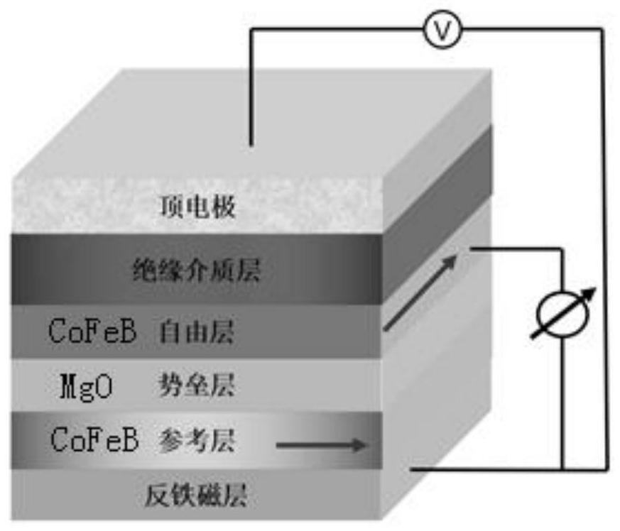
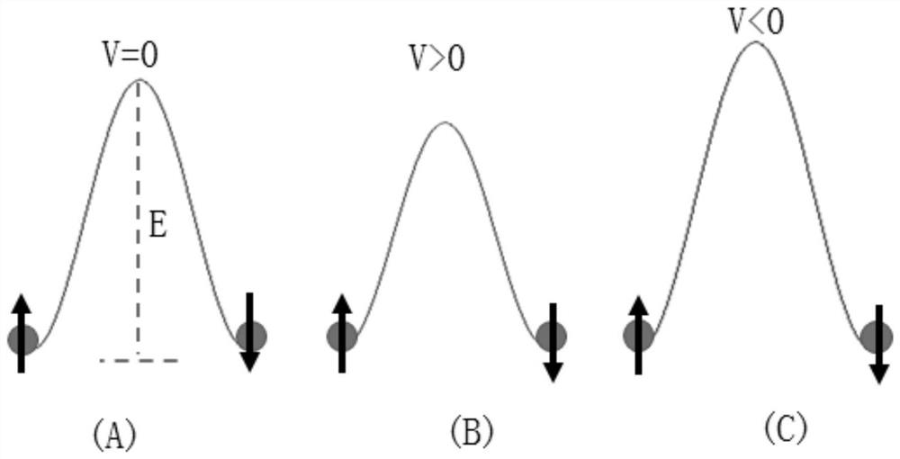
The present application discloses a control method for a tunneling magnetoresistance sensor, including: applying a voltage between the bottom electrode and the top electrode of the tunneling magnetoresistance sensor, the voltage being a variable voltage provided by an adjustable power supply; adjusting the The voltage value between the bottom electrode and the top electrode is used to adjust the range and sensitivity of the tunneling magnetoresistive sensor. The method is based on an adjustable power supply applying a voltage between the bottom electrode and the top electrode of the tunneling magnetoresistance sensor, and by adjusting the applied voltage value, the coupling of the vertical anisotropy of the interface of the magnetic tunnel junction in the tunneling magnetoresistance sensor is changed. Coefficient, through which the vertical anisotropy energy of the interface can be adjusted, and then the magnetic anisotropy energy of the magnetic tunnel junction can be adjusted, so that the sensitivity and linear region of the tunneling magnetoresistive sensor are adjusted accordingly, without additional compensation circuits, The overall complexity of the magnetic detection system is reduced. Correspondingly, the present application also discloses a control system for the tunneling magnetoresistive sensor.

Description

technical field [0001] The present application relates to the field of semiconductors, in particular to a control method and system for a tunneling magnetoresistance sensor. Background technique [0002] Weak magnetic detection is an important part of modern detection technology in the 21st century. Weak magnetic detection technology is used in military affairs, resource exploration, space environment detection and other scientific research fields. The weak magnetic detection system is generally composed of a magnetic sensor, a signal conditioning module, a signal acquisition module and a signal analysis module. The function of the magnetic sensor is to convert the magnetic field signal into an electrical signal. The sensitivity of the magnetic sensor determines the detection accuracy of the overall system, and the saturation magnetic field of the magnetic sensor determines the detection range of the overall system. [0003] Generally speaking, for different magnetic field...

Claims


Application Information

Patent Timeline
Patent Type & Authority Patents(China)
IPC IPC(8): G01R35/00G01R33/09
CPCG01R33/098G01R35/005
Inventor 崔岩罗军杨美音许静
Owner INST OF MICROELECTRONICS CHINESE ACAD OF SCI
Learn More