Omnidirectional WLAN antenna with common-mode current suppression

A common-mode current and antenna technology, applied in the field of antennas, can solve problems such as pattern distortion, achieve the effects of reducing out-of-roundness, reducing physical size, and suppressing common-mode current

Inactive Publication Date: 2019-08-09
XIDIAN UNIV
View PDF2 Cites 0 Cited by
  • Summary
  • Abstract
  • Description
  • Claims
  • Application Information

AI Technical Summary

Problems solved by technology

It is used to solve the technical problem of pattern distortion caused by the unbalanced current on the outer surface of the coaxial line

Method used


Image

  • Omnidirectional WLAN antenna with common-mode current suppression
  • Omnidirectional WLAN antenna with common-mode current suppression
  • Omnidirectional WLAN antenna with common-mode current suppression

Examples


Embodiment 1

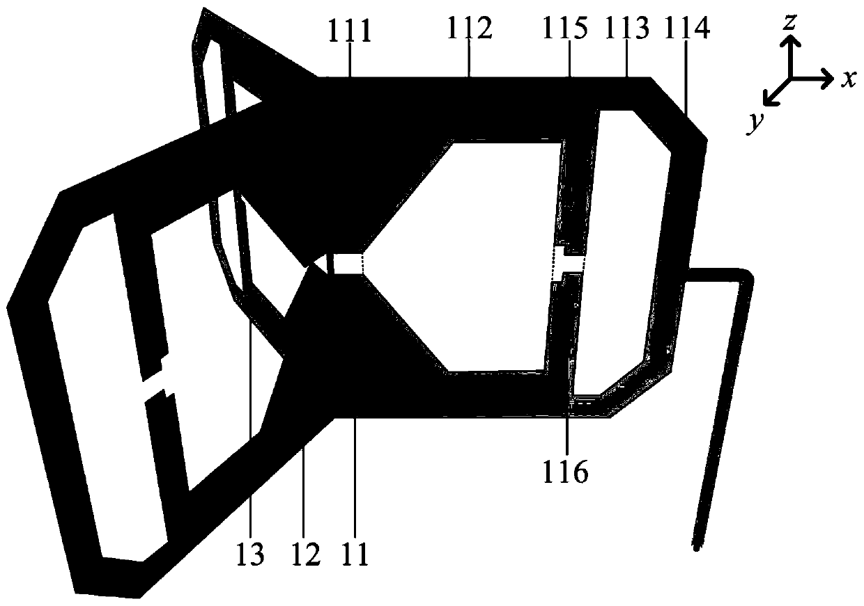
[0031] refer to figure 1 , figure 2 and image 3

[0032] An omnidirectional WLAN antenna based on common mode current suppression, comprising a radiation structure 1 and a coaxial line 2, the radiation structure 1 is composed of three first radiation units 11, second radiation units 12 and third radiation units of the same structure Each radiating unit is provided with three feeding ports 111 of the same structure, a first polygonal slot 112, a second polygonal slot 113 and two identical cut corners 114, and the feeding ports One side of 111 is connected to the axis of the Z axis;

[0033] Between the first polygonal groove 112 and the second polygonal groove 113, metal branches 115 are respectively provided, and the center positions of the metal branches 115 are respectively provided with notches 116, and are distributed symmetrically about the axis of the X axis; One end of the coaxial line 2 is introduced along one side of the feeding port 111 and distributed along th...

Embodiment 2

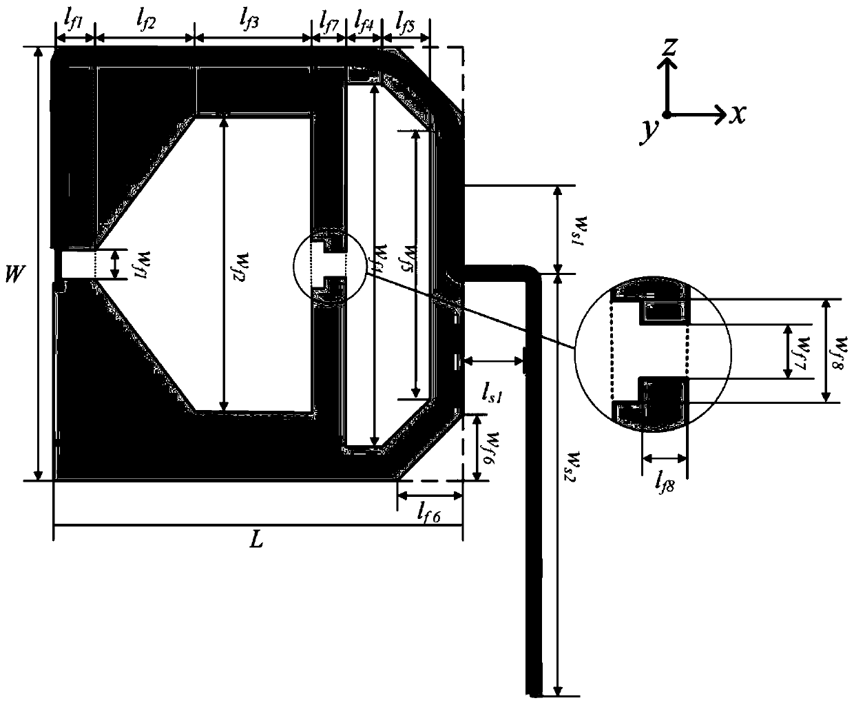
[0048] The width of the metal branch 115 is expressed as lf7, wherein the value range of lf7 is 1-5 mm. In the present invention, lf7=1mm.

[0049] The notch 116 is in a stepped shape, the first step width is expressed as wf7, and the length is expressed as lf8; the second step width is expressed as wf8, wherein the value range of wf7 is 0.5-4mm, and the value range of lf8 is 1- 4mm, the value range of wf8 is 1~5mm. In the present invention, wf7=0.5mm, wf8=1mm, and lf8=1mm.

[0050] The said coaxial line 2, the variation range of the position of the leading end and the XOY plane with respect to the Z axis is expressed as ws1, wherein the value range of ws1 is -10-10mm. In the present invention, ws1=-10mm.

[0051] The coaxial cable 2 is welded on the surface of the radiation unit 11 .

[0052] The two same cut corners 114 are located on the corresponding side of the feed port 111, and the lengths of the right-angle sides of the cut corners are expressed as lf6 and wf6, whe...

Embodiment 3

[0057] The width of the metal branch 115 is expressed as lf7, wherein the value range of lf7 is 1-5 mm. In the present invention, lf7=5mm.

[0058] The notch 116 is in a stepped shape, the first step width is expressed as wf7, and the length is expressed as lf8; the second step width is expressed as wf8, wherein the value range of wf7 is 0.5-4mm, and the value range of lf8 is 1- 4mm, the value range of wf8 is 1~5mm. In the present invention, wf7=4mm, wf8=5mm, and lf8=4mm.

[0059] The said coaxial line 2, the variation range of the position of the leading end and the XOY plane with respect to the Z axis is expressed as ws1, wherein the value range of ws1 is -10-10 mm. In the present invention, ws1=+10mm.

[0060] The coaxial cable 2 is welded on the surface of the radiation unit 11 .

[0061] The two same cut corners 114 are located on the corresponding side of the feed port 111, and the lengths of the right-angle sides of the cut corners are expressed as lf6 and wf6, wher...


PUM


Abstract

The invention provides an omnidirectional WLAN (Wireless Local Area Networks) antenna with common-mode current suppression. The antenna comprises a radiation structure and a coaxial line, the radiation structure is formed by a first radiation unit, a second radiation unit and a third radiation unit (13) which have the same structure; each radiation unit is provided with three feed ports with the same structure, a first polygonal groove, a second polygonal groove and two same cutting angles; metal branches are arranged between the first polygonal grooves and the second polygonal grooves, the centers of the metal branches are provided with gaps; one end of the coaxial line is led in along one sides of the feed ports and is distributed at the edges of the first radiation units, and the otherend of the coaxial line is led out along the opposite sides of the feed ports and is connected with an SMA joint. The omnidirectional WLAN antenna can suppress the common mode current on the outer surface of the feed coaxial line and can reduce the distortion of the antenna directional diagram while meeting the performance of the omnidirectional WLAN antenna, and can be used for a wireless local area network communication system.

Description

technical field [0001] The invention belongs to the technical field of antennas, and in particular relates to an omnidirectional WLAN antenna with common-mode current suppression, which can be applied to a wireless local area network communication system. Background technique [0002] In recent years, with the development of wireless communication, WLAN (Wireless Local Area Networks), a communication technology, has been widely used, and antennas working in WLAN frequency bands have also attracted extensive research. In engineering design, the main performance indicators of WLAN antennas are measured by working bandwidth and directivity. The WLAN protocol has two operating frequency bands, 2.4GHz and 5GHz. According to different application scenarios, omnidirectional WLAN antennas are usually used in small places such as indoors, and directional WLAN antennas are usually used in large places such as outdoors. [0003] The traditional WLAN omnidirectional antenna, due to the...

Claims


Application Information

Patent Timeline
Patent Type & Authority Applications(China)
IPC IPC(8): H01Q1/36H01Q1/50
CPCH01Q1/36H01Q1/50
Inventor 翁子彬宋文亮张立高阳焦永昌
Owner XIDIAN UNIV
Why Eureka
Try Eureka