
Weight-optimized steel piston

A technology for pistons and piston pin seats, which is applied in the direction of pistons, cylindrical pistons, plungers, etc., can solve the problems of unsatisfactory weight of pistons, and achieve the effects of weight reduction and simplified manufacturing methods

Inactive Publication Date: 2019-08-09
KOLBENSCHMIDT AG
View PDF10 Cites 0 Cited by
  • Summary
  • Abstract
  • Description
  • Claims
  • Application Information

AI Technical Summary

Problems solved by technology

However, such a piston is still unsatisfactory in terms of its weight

Method used


Image

  • Weight-optimized steel piston
  • Weight-optimized steel piston
  • Weight-optimized steel piston

Examples


Embodiment Construction

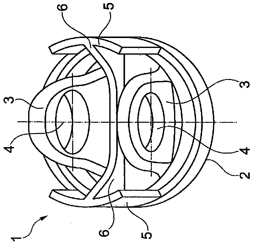
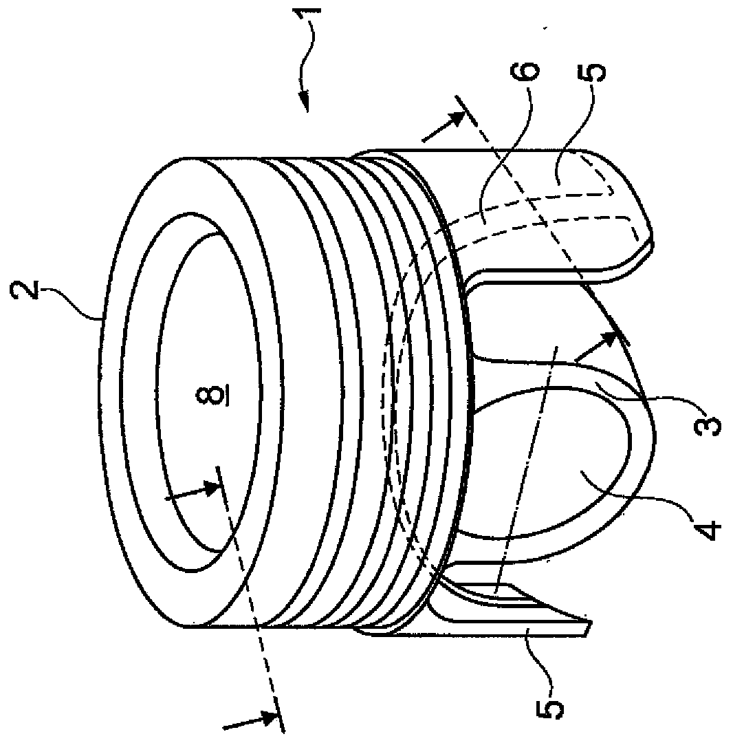
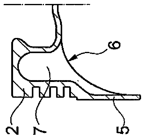
[0013] in Figure 1 to 4 A first embodiment of a piston 1 of an internal combustion engine is shown in FIG. The piston 1 has an upper part 2 which has: a piston pin seat 3 suspended thereon, in which there are pin holes 4 respectively; and a skirt wall section 5 that plays a bearing role. In this embodiment, the load-bearing skirt wall section 5 is unsupported on the upper part 2 on three sides, wherein the fourth side (one-piece or attached) is directly connected to the upper part 2 Part 2, especially connected to the underside of the upper part. The load-bearing skirt wall section 5 is supported by ribs 6 extending from the underside of the upper part 2 toward the load-bearing skirt wall section 5. The ribs 6 are formed symmetrically in the center and extend through the piston stroke axis.

[0014] in Figure 1 to 4 The piston 1 shown in may have (but does not necessarily have) a cooling channel 7 and a combustion chamber cavity 8. If a cooling channel 7 is present, it is clos...


PUM


Abstract

The invention relates to a piston (1) of an internal combustion engine, having an upper part (2) with appended piston bosses (3) and load-bearing skirt wall sections (5), wherein the load-bearing skirt wall sections (5) are arranged in a self-supporting manner on the upper part (2) without any attachment to the piston bosses (3), and wherein a rib (6) extends from the underside of the upper part (2) in the direction of the inner side of the load-bearing skirt wall sections (5).

Description

Technical field [0001] The invention relates to a piston of an internal combustion engine according to the features of the preamble of claim 1, which has an upper part with a piston pin seat suspended on the upper part and a skirt wall section that functions as a bearing. Background technique [0002] Pistons used in internal combustion engines are either cylindrical completely surrounding piston skirts, which are arranged (suspended) below the upper part of the piston. Or there are pistons in a so-called box design, wherein such pistons have a supporting skirt section, so that their piston skirts are only partially present and are not completely cylindrical. The supporting skirt wall section is connected to the piston pin seat in its unsupported edge region by a connecting wall extending toward the piston pin seat. This achieves the required support of the supporting skirt wall section in the cylinder of the internal combustion engine during operation of the piston. For this p...

Claims


Application Information

Patent Timeline
IPC IPC(8): F02F3/00
CPCF02F3/0076F16J1/005
Inventor A·哈伯尔T·托马森
Owner KOLBENSCHMIDT AG
Learn More