power transmission control

A power transmission and control device technology, which is applied in transmission control, motor vehicles, transportation and packaging, etc., and can solve problems such as discomfort and collision sound for drivers

Active Publication Date: 2021-02-02
AISIN AW CO LTD
View PDF5 Cites 0 Cited by
  • Summary
  • Abstract
  • Description
  • Claims
  • Application Information

AI Technical Summary

Problems solved by technology

In addition, if the Image 6 If the sleeve and the gear are forcibly meshed in the state, there is a problem that the front ends of the sleeve and the gear collide with each other and the driver feels uncomfortable.

Method used


Image

  • power transmission control
  • power transmission control
  • power transmission control

Examples


no. 1 Embodiment approach

[0030] Hereinafter, an example of the power transmission control device 10 according to the first embodiment will be described with reference to the drawings. figure 1 It is an explanatory diagram showing the configuration of a vehicle related to the power transmission control device 10 of the present invention. exist figure 1 Among them, 11 is an engine as a power source, 12 is an input shaft as a first rotating shaft, 13 is a motor generator as another power source, 14 is a sleeve as a joint member, 15 is a fork, and 16 is a 17 is a shock absorber, 18 is an actuator, 19a and 19b are power transmission mechanisms, 20 is an output shaft as a second rotating shaft, and 21 is an engine control unit (hereinafter ECU) as a control part. To the input shaft 12 , an idler gear GA1 and an idler gear GB1 , which are engaged members, are connected so as to be relatively rotatable, and to the output shaft 20 , gears GA2 and GB2 are connected so as to be integrally rotatable. The firs...

no. 2 Embodiment approach

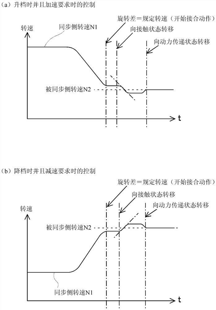
[0057] Next, an example of the power transmission control device 10 according to the second embodiment will be described with reference to the drawings. The configuration of the power transmission control device 10 according to the second embodiment and figure 1 are the same, so descriptions are omitted. This second embodiment is different from the first embodiment in that the synchronous-side rotational speed N1 and the synchronized-side rotational speed N2 are brought into agreement, and the transition to the contact state is started, and the synchronous-side rotational speed is controlled so that a rotation difference occurs after the contact state transition. N1.

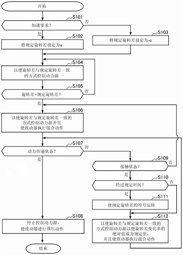
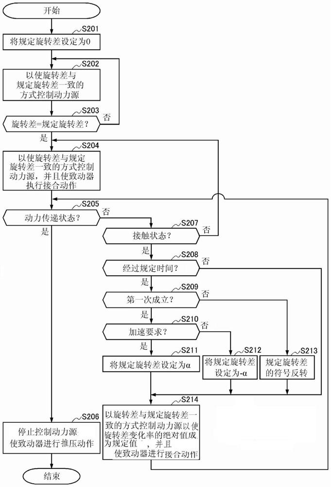
[0058] Figure 4 It is a flowchart showing the flow of engagement operation control of the power transmission control device 10 according to the second embodiment of the present invention. The engagement operation control by the power transmission control device 10 according to the present invention starts f...


PUM


Abstract

The present invention provides a power transmission control device capable of reliable gear engagement in a transmission based on an asynchronous transmission. It is a power transmission control device applied in a non-synchronous transmission vehicle with at least two gears, in order to perform the acquisition of the rotation speed information of the idler wheel as the engaged component and the rotation speed information of the sleeve as the engaging component, which will be able to The speed of one side fluctuated by the power source is set as the speed of the synchronous side, and the speed of the other side is set as the speed of the synchronized side. After a gear shift request is made and the power transmission is released, the speed of the synchronous side is changed by the power source to make the speed of the synchronous side and the driven side change. The rotation difference of the synchronous side rotation speed coincides with the predetermined rotation difference, and the engagement operation is performed in such a manner that the contact state is transferred to the power transmission state, and when a predetermined time has elapsed after the transition to the contact state, the sign of the predetermined rotation difference is reversed, The power transmission state is shifted to the power transmission state while performing control to match the predetermined rotation difference after the sign is reversed to the rotation difference.

Description

technical field [0001] The present invention relates to a power transmission control device in a vehicle in which AMT is controlled by an actuator and the transmission does not have a synchronizing mechanism. Background technique [0002] In recent years, the number of vehicles equipped with mechanical automatic transmissions (AMTs) that control gears by actuators has increased, and AMTs are being developed as transmissions that do not have a synchronizer gear mechanism including a synchronizer ring. Transmission (non-synchronized transmission). When the gears in a vehicle using such an actuator are changed, the idler gear of the current shift stage is fixed so that it cannot be rotated relative to the rotation shaft by using the power from the actuator. Pull out the sleeve of the idler gear of the shift gear so that the idler gear and the rotating shaft can rotate relative to each other. And, in order to switch to the next gear, the sleeve moved to the neutral position sl...

Claims


Application Information

Patent Timeline
Patent Type & Authority Patents(China)
IPC IPC(8): F16H61/04F16H59/46F16H61/68F16H63/50
CPCF16H61/04F16H59/46F16H61/68F16H63/502F16H2059/462F16H63/50F16H61/0403B60Y2200/92F16H59/74F16H2059/6853F16H2059/706F16H2059/743
Inventor 井上大贵
Owner AISIN AW CO LTD
Why Eureka
Try Eureka