Threading device for measuring three-dimensional coordinates of pipe

A technology of three-dimensional coordinates and measuring pipes, which is applied in the field of threaders, can solve the problems of inconvenient carrying, unsafe, large size, etc., and achieve the effect of convenient carrying, convenient operation and strong operability

Pending Publication Date: 2019-08-13
佛山市华禅能燃气设计有限公司
View PDF0 Cites 7 Cited by
  • Summary
  • Abstract
  • Description
  • Claims
  • Application Information

AI Technical Summary

Problems solved by technology

However, because the threading process of the pipe pass is very laborious, it needs three people to operate at the same time, and there are still disadvantages such as unsafe, bulky, inconvenient to carry, and the threading length is ≤ 100 meters. Therefore, the existing technology needs to be further improved and perfected.

Method used


Image

  • Threading device for measuring three-dimensional coordinates of pipe
  • Threading device for measuring three-dimensional coordinates of pipe
  • Threading device for measuring three-dimensional coordinates of pipe

Examples


Embodiment 1

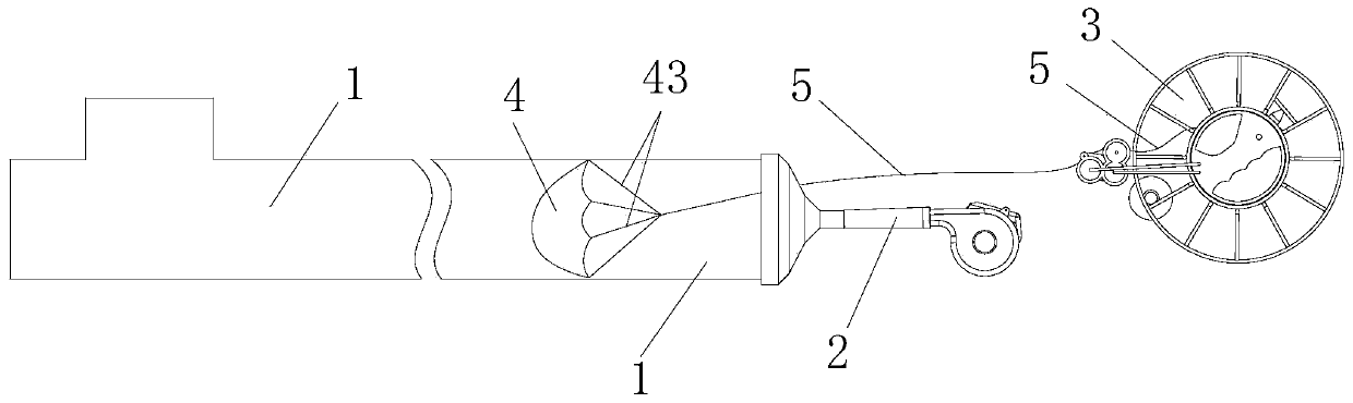
[0063] Such as figure 1 As shown, this embodiment discloses a threader for measuring three-dimensional coordinates of a pipeline, the threader mainly includes an air blast device 2 for blowing air to the pipeline to be measured, a lead wire 5, and a traction device 4 for bearing directional wind , and a wire reel 3 for receiving and releasing the lead wire 5 . One end of the lead wire 5 passes through the blower device 2 and is fixedly connected to the traction device 4 , and the other end is spirally wound in the winding reel 3 . The traction device 4 is put into one end of the pipeline to be tested, and the head of the blower device 2 is sleeved on the end of the pipeline to be tested, blowing air to the other end of the pipeline to be tested, and simultaneously with the reel 3 to set off the wire, the The pulling device 4 and the lead wire 5 are blown to the other end of the pipeline to be tested together.

[0064] Specifically, the pulling device 4 is set as an ordinary ...


PUM


Abstract

The invention discloses a threading device for measuring three-dimensional coordinates of a pipe. The threading device mainly comprises an air blowing device, a lead wire, a traction device and a take-up reel; one end of the lead wire passes through the air blowing device to be fixedly connected with the traction device, and the other end of the lead wire is spirally wound in the take-up reel; andthe traction device is placed at one end of the pipe to be tested, and the head of the air blowing device is arranged at the end of the pipe to be tested in a sleeving manner. In the using process, aKevlar line is tied to a special U-shaped lightweight plastic bag to be placed into one end of the pipe, a sleeve head is arranged on a pipe opening in a sleeving manner, an air blower connected to abattery is aligned with a large hole of the sleeve head to blow air into the U-shaped bag at the pipe opening until the U-shaped bag is blown to the other end of the pipe, and threading is finished.After the Kevlar line threaded into the pipe is connected to a traction steel rope, the traction steel rope is replaced in the pipe, then the traction steel rope is connected to a measuring host, themeasuring host is pulled to slide from one end of the pipe to the other end of the pipe, and data collection is finished after dragging by the traction steel rope and running in the pipe by one roundtrip.

Description

technical field [0001] The invention relates to the technical field of three-dimensional measurement of pipelines, in particular to a threader for measuring three-dimensional coordinates of pipelines. Background technique [0002] Inertial gyroscope positioning technology is an internationally leading precise positioning technology for pipelines. It can automatically generate spatial curves of underground pipelines based on x, y, and z three-dimensional coordinates to achieve accurate positioning of deep buried pipelines without being limited by pipeline materials. If you need to obtain the exact depth of a certain position of the pipeline, you only need to measure the ground elevation above the point, and subtract the z-coordinate of the point generated by the inertial gyroscope positioning technology from the ground elevation to obtain the exact buried depth of the pipeline at this point. The inertial gyroscope positioning technology consists of two parts: hardware and sof...

Claims


Application Information

Patent Timeline
Patent Type & Authority Applications(China)
IPC IPC(8): B65H51/16B65H57/14B65H75/40B65H75/44G01B21/00
CPCB65H51/16B65H57/14B65H75/406B65H75/4428B65H2701/36G01B21/00
Inventor 郑光耀王建业陈碧涛窦中亮邓博艺石炜明张玉李达儒
Owner 佛山市华禅能燃气设计有限公司
Why Eureka
Try Eureka