
Engine gear train and engine gear train control method

A control method and engine technology, applied in the direction of engine control, machine/engine, mechanical equipment, etc., can solve the problems of generator 6' failure, power consumption, damage to battery life, etc., so as to solve the problem of insufficient power generation and reduce speed The effect of output and increase in power generation

Active Publication Date: 2020-09-29
WEICHAI POWER CO LTD
View PDF5 Cites 0 Cited by
  • Summary
  • Abstract
  • Description
  • Claims
  • Application Information

AI Technical Summary

Problems solved by technology

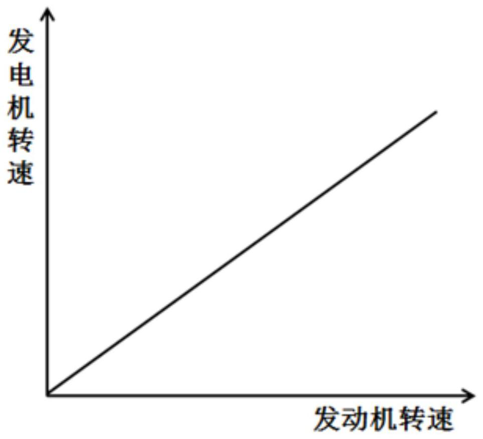
[0004] like figure 2 As shown, the engine speed and the generator 6' speed in the existing engine wheel train satisfy a linear relationship, so that the speed ratio of the engine wheel train is constant. When the engine is running, it will always drive the generator 6' to do work, consume power, and cause energy waste
When the engine is running at a low speed, when the vehicle consumes a lot of electricity (for example, when the air conditioner is turned on in summer), the generator 6' rotates at a low speed, and the power generation is insufficient, which will easily cause the battery to lose power, affect the use of the vehicle, and damage the life of the battery ; When the engine is running at high speed, it is easy to cause the generator 6' to overspeed, which will cause the failure of the generator 6' to rise, thereby damaging the life of the generator 6'
Therefore, due to the constant speed ratio of the existing engine gear train, it is impossible to take into account the following two problems: the use of a small speed ratio gear train has the problem of insufficient power generation at low speeds, and the use of a large speed ratio gear train has the generator 6 'Overspeed problem

Method used


Image

  • Engine gear train and engine gear train control method
  • Engine gear train and engine gear train control method
  • Engine gear train and engine gear train control method

Examples


Embodiment Construction

[0046]In order to make the technical problems solved by the present invention, the technical solutions adopted and the technical effects achieved clearer, the technical solutions of the embodiments of the present invention will be further described in detail below in conjunction with the accompanying drawings. Obviously, the described embodiments are only the technical solutions of the present invention. Some, but not all, embodiments. Based on the embodiments of the present invention, all other embodiments obtained by those skilled in the art without creative efforts fall within the protection scope of the present invention.

[0047] In the description of the present invention, unless otherwise clearly specified and limited, the terms "connected", "connected" and "fixed" should be understood in a broad sense, for example, it can be a fixed connection, a detachable connection, or an integrated ; It can be a mechanical connection or an electrical connection; it can be a direct ...


PUM


Abstract

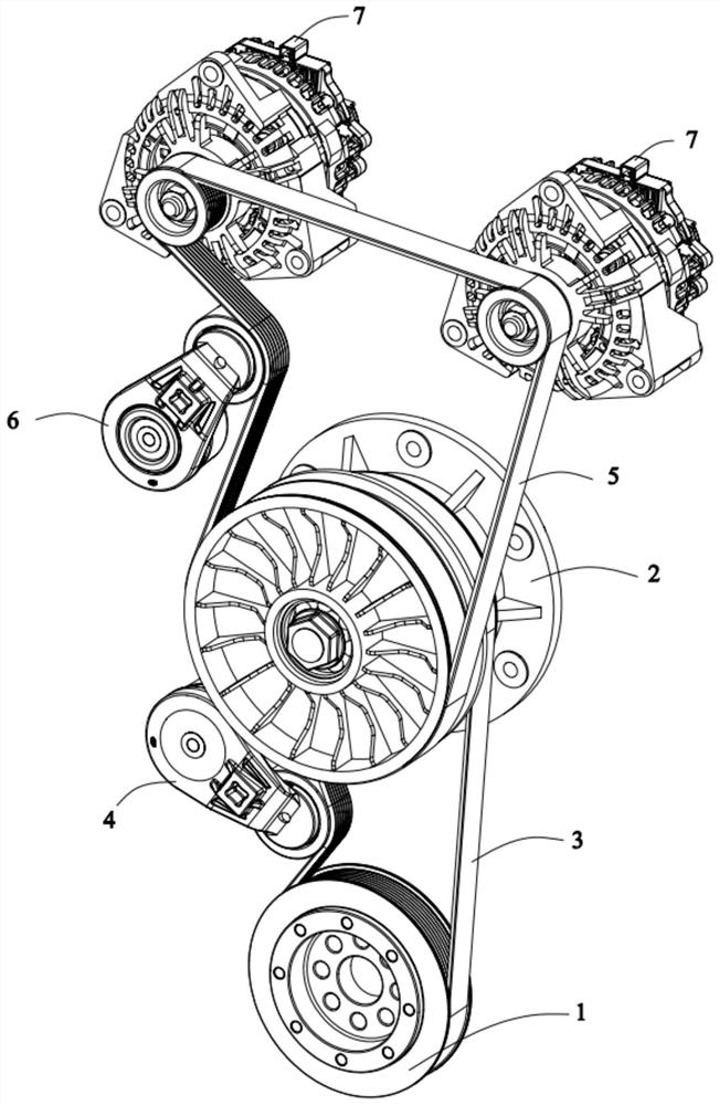
The invention belongs to the technical field of engines, and discloses an engine wheel train and an engine wheel train control method. The engine wheel train comprises a crankshaft pulley, a transition wheel and a power generator; the transition wheel comprises a main shaft, and an inner sheave is fixedly mounted on the main shaft and is in transmission connection with a first belt; an outer sheave is in transmission connection with a second belt and can rotate relative to the main shaft; a first transmission set can rotate relative to the main shaft, one end of the first transmission set is configured to be selectively connected to the inner sheave, and the other end of the first transmission set is connected to the outer sheave, so that the rotating speed of the outer sheave is the sameas that of the inner sheave; and a second transmission set can rotate relative to the main shaft, one end of the second transmission set is configured to be selectively connected to the inner sheave,and the other end of the second transmission set is connected to the outer sheave through an adsorption assembly, so that the rotating speed of the outer sheave is smaller than that of the inner sheave. The engine wheel train can ensure the low-speed power generation of the engine, can avoid the problem of overspeed of the power generator, and accordingly adjusts the power generation of the powergenerator.

Description

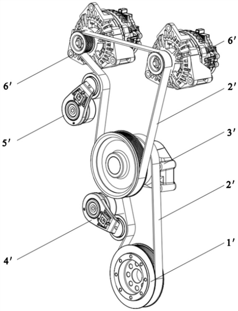
technical field [0001] The invention relates to the technical field of engines, in particular to an engine gear train and an engine gear train control method. Background technique [0002] The engine gear train refers to the system that uses the friction between the V-ribbed belt and the pulley to transmit the power of the engine to the accessories and make it run at a suitable speed. [0003] Such as figure 1 As shown, the existing engine gear train includes crankshaft pulley 1', V-ribbed belt 2', transition pulley 3', first tensioner 4', second tensioner 5' and generator 6', crankshaft pulley 1' Installed on the crankshaft of the engine, it is used to drive the wheel train. Both the first tensioning pulley 4' and the second tensioning pulley 5' are provided with a coil spring structure, which is used to apply a certain force to the V-ribbed belt 2' to tension the V-ribbed belt 2'. The crankshaft pulley 1' is connected to the transition wheel 3' through the V-belt 2', an...

Claims


Application Information

Patent Timeline
Patent Type & Authority Patents(China)
IPC IPC(8): F02B67/06F02B63/04F02D29/06
CPCF02B63/04F02B67/06F02D29/06
Inventor 张孟扬栗明张文通蔡君辉
Owner WEICHAI POWER CO LTD
Learn More