An embedded permanent magnet array axial eddy current damper

An eddy current damper, permanent magnet array technology, applied in the direction of magnetic spring, spring/shock absorber, mechanical equipment, etc., can solve the problems of poor heat dissipation, inconvenient installation and disassembly, difficult installation and positioning, etc., and achieves reasonable structural design and convenience. The effect of installation and disassembly and improvement of heat dissipation conditions

Active Publication Date: 2020-11-13
NANJING UNIV OF SCI & TECH
View PDF6 Cites 0 Cited by
  • Summary
  • Abstract
  • Description
  • Claims
  • Application Information

AI Technical Summary

Problems solved by technology

[0003] Some guide rail devices and piston devices bear impact loads and high-speed loads, requiring strong braking force, such as rear seat brakes for artillery, high-altitude anti-drop devices, etc., which are often large in size and mass, and are inconvenient to install and disassemble.
The permanent magnet electromagnetic damper used for linear braking can generally be divided into flat plate type and cylindrical type according to the structure. The general structure and principle of the flat type are generally based on the relative movement between the permanent magnet array attached to the back plate and the conductor plate. To generate damping force, but the volume is generally large, and the installation and positioning are difficult
Cylindrical dampers generally use ring-shaped permanent magnet arrays. The permanent magnets are connected in series on the moving shaft to generate damping relative to the coaxial conductor cylinder. The utilization rate of the permanent magnets is high, but the mass of the moving shaft and the outer cylinder is often large and Poor heat dissipation

Method used


Image

  • An embedded permanent magnet array axial eddy current damper
  • An embedded permanent magnet array axial eddy current damper
  • An embedded permanent magnet array axial eddy current damper

Examples


Embodiment Construction

[0035] Below in conjunction with appendix and specific embodiment, further illustrate the present invention, should be understood that these embodiments are only for illustrating the present invention and are not intended to limit the scope of the present invention, after having read the present invention, those skilled in the art will understand various aspects of the present invention Modifications in equivalent forms all fall within the scope defined by the appended claims of this application.

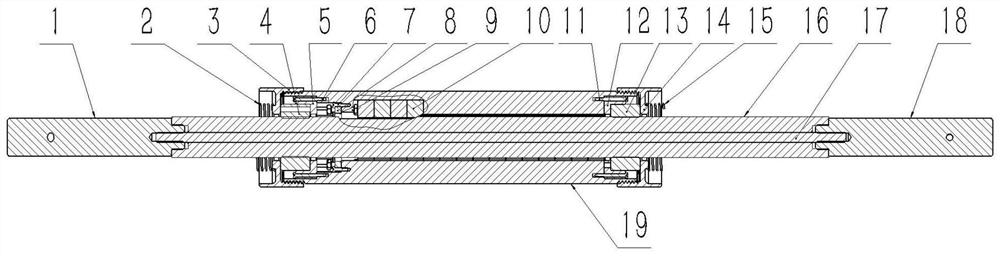
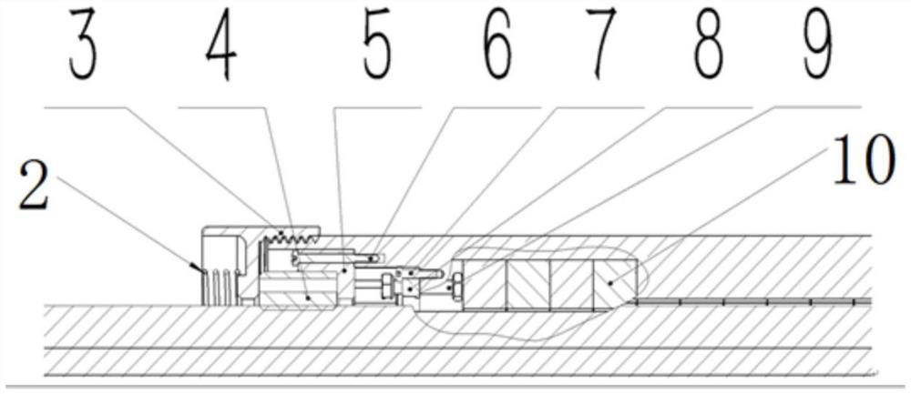
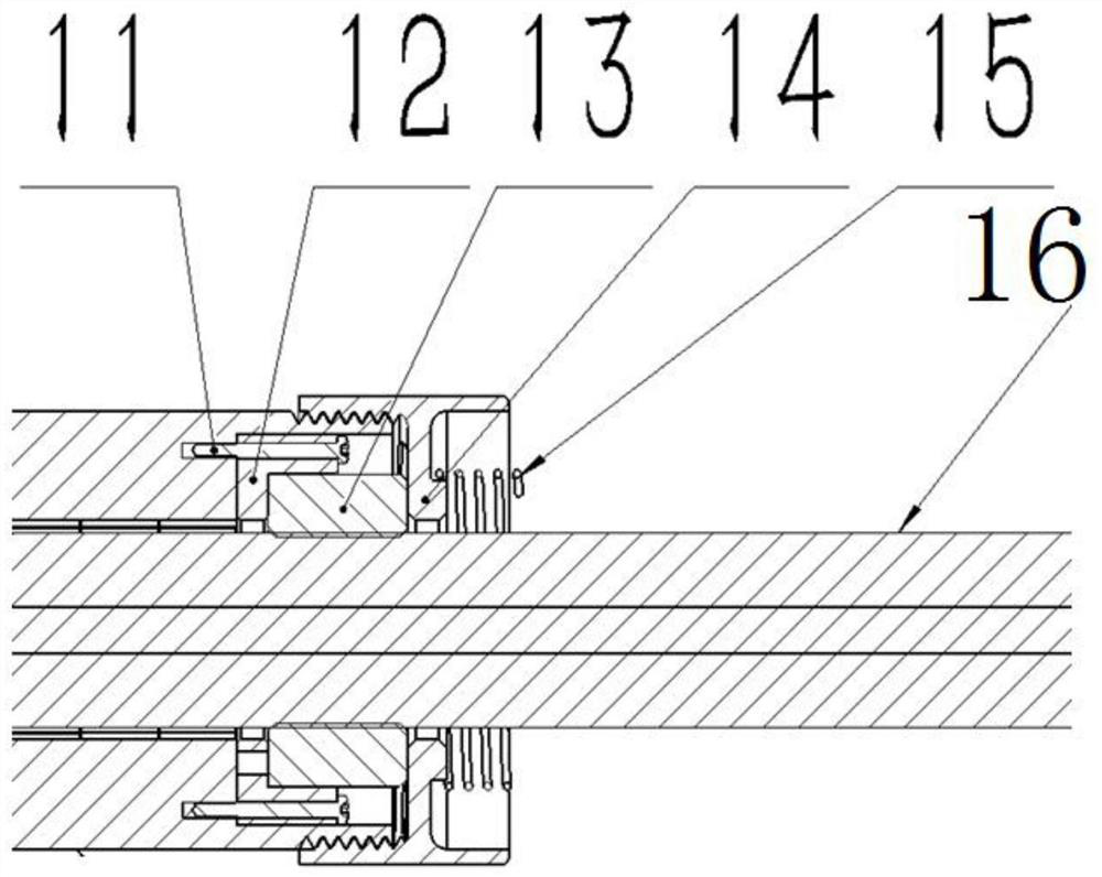
[0036] Such as Figure 1-3 As shown, an embedded permanent magnet array axial eddy current damper is characterized in that it includes a motion shaft assembly and a magnetic field source assembly, the motion shaft assembly is coaxially arranged with the magnetic field source assembly, and the motion shaft assembly includes The first end shaft 1, the second end shaft 18, the conductor cylinder 16 and the iron core 17, the conductor cylinder 16 is arranged through the magnetic field s...


PUM


Abstract

The invention discloses an embedded permanent magnet array axial eddy current damper. The embedded permanent magnet array axial eddy current damper comprises a motion shaft module and a magnetic fieldsource module; the motion shaft module and the magnetic field source module are coaxially arranged; the motion shaft module comprises a first end shaft, a second end shaft, a guide cylinder and an iron core; the guide cylinder is arranged by penetrating through the magnetic field source module; the first end shaft and the second end shaft are fixedly connected with two ends of the guide cylinder;the iron core penetrates through the guide cylinder, and two ends of the iron core are positioned in the first end shaft and the second end shaft; the magnetic field source module comprises an outercylinder, a positioning part and multiple permanent magnets; the guide cylinder penetrates through the outer cylinder; the positioning part is used for realizing radial and peripheral positioning of the guide cylinder; multiple lines of through grooves are arranged in the outer cylinder; the multiple permanent magnets are positioned in the multiple lines of through grooves; and magnetizing directions of the multiple permanent magnets are arranged according to Halbach arrays. The embedded permanent magnet array axial eddy current damper is reasonable, simple and reliable in structural design, easy to manufacture and convenient to install and disassemble, and can generate higher damping force and damping mass ratio through the Halbach permanent magnet arrays.

Description

technical field [0001] The invention belongs to the technical field of electromagnetic braking, in particular to an embedded permanent magnet array axial eddy current damper. Background technique [0002] According to the law of electromagnetic induction, when the conductor material and the magnetic field move relative to each other, an eddy current will be induced in the conductor, and the eddy current will excite an induced magnetic field. The role of the induced magnetic field is to hinder the relative movement between the conductor and the main magnetic field. A damping force (braking force). And the conductor material has resistance, and the eddy current will be dissipated in the form of heat energy. The eddy current damper is an inductive energy dissipation device based on the above principle, which is mainly used in the fields of electromagnetic braking and vibration suppression. [0003] Some guide rail devices and piston devices are subject to impact loads and hig...

Claims


Application Information

Patent Timeline
Patent Type & Authority Patents(China)
IPC IPC(8): F16F6/00
CPCF16F6/005
Inventor 李昶昊刘宁董关杨国来
Owner NANJING UNIV OF SCI & TECH
Why Eureka
Try Eureka