Physical unclonable function circuit for CMOS dynamic visual image sensor

A visual image and functional circuit technology, applied in the field of security, can solve problems such as poor reliability, achieve high reliability, good uniqueness, and improve reliability

Inactive Publication Date: 2019-08-13
SHENZHEN UNIV
View PDF4 Cites 2 Cited by
  • Summary
  • Abstract
  • Description
  • Claims
  • Application Information

AI Technical Summary

Problems solved by technology

Considering the various harsh environments involved in DVS applic

Method used


Image

  • Physical unclonable function circuit for CMOS dynamic visual image sensor
  • Physical unclonable function circuit for CMOS dynamic visual image sensor
  • Physical unclonable function circuit for CMOS dynamic visual image sensor

Examples


Embodiment

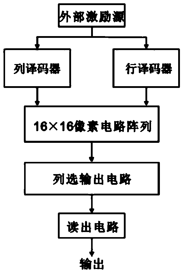
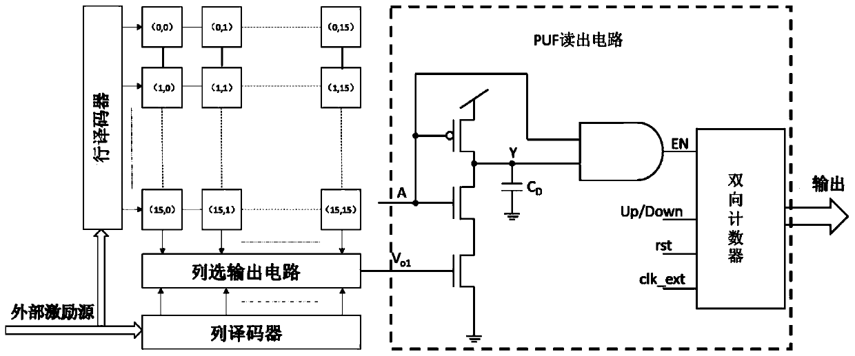
[0028] like figure 1 , 2 As shown, the PUF structure circuit proposed in this paper, a dark current physical unclonable function circuit, includes an external excitation source, a column decoder, a row decoder, a 16-by-16 pixel circuit array, a column selection output circuit, a readout circuit; the readout circuit includes a digital voltage comparator and a bidirectional counter. Among them, each row or column of the pixel circuit array is composed of 16 pixel circuits, including a total of 256 pixel circuits, and the pixel circuit array is responsible for generating 256 output voltages V o1 ; Through the external excitation source, the row and column decoders decode the row and column addresses respectively, the row selection signal output by the row decoder performs row selection on the pixel circuits in the array, and the V of all column pixel circuits in the selected row is selected. o1 is loaded on the column output bus of each column of the array; the column decoder p...


PUM


Abstract

The invention provides a physical unclonable function circuit for a CMOS dynamic visual image sensor. The physical unclonable function circuit comprises an external excitation source, a column decoder, a row decoder, a 16 * 16 pixel circuit array, a column selection output circuit and a reading circuit. The pixel circuit array comprises 256 pixel circuits in total, and the pixel circuit array is responsible for generating 256 output voltages Vo1; row selection signals output by the row decoder are used for carrying out row selection on pixel circuits in an array, the column decoder is used forcarrying out column selection on the column selection output circuit, and the reading circuit is used for calculating a difference value of Vo1 of two pixels selected front and back and quantizing the difference value to serve as response output of a PUF. According to the pixel circuit, the logarithmic converter in the array is extremely insensitive to fluctuation of power supply voltage, the reliability of PUF to the power supply voltage is greatly improved, unstable output response bits can be identified and filtered out through a threshold method, and therefore the reliability, especiallythe reliability to the temperature, can be further improved.

Description

[0001] [Technical field] [0002] The invention relates to the field of security technology, in particular to a physical unclonable function circuit for a CMOS dynamic vision image sensor. [0003] [Background technique] [0004] Today, visual sensor networks are expanding and ubiquitous. Thanks to advances in integrated circuits and technology, the quality of cameras has become better and more reliable, and their manufacturing costs have dropped dramatically. However, in some related application fields, such as traffic monitoring and intelligent assisted living, traditional frame-based imaging technology can no longer meet the requirements. In public surveillance scenarios in the field of transportation applications, in the face of rapidly changing scenarios, the performance of traditional frame-based imaging technology is mainly limited by its limited dynamic range and bandwidth; while in intelligent assisted living In the private surveillance scene in the application field...

Claims


Application Information

Patent Timeline
IPC IPC(8): H04N5/374H04N5/378H04L9/32
CPCH04L9/3278H04N25/76H04N25/75
Inventor 赵晓锦郭占江章洁云
Owner SHENZHEN UNIV
Why Eureka
Try Eureka