High-resolution 3D radar wave imaging device

An imaging device, radar wave technology, used in sensing applications to solve problems such as increased complexity

Pending Publication Date: 2019-08-13
IEE INT ELECTRONICS & ENG SA
View PDF22 Cites 13 Cited by
  • Summary
  • Abstract
  • Description
  • Claims
  • Application Information

AI Technical Summary

Problems solved by technology

[0015] In the case of radar signal generation and detection, the manufacturing complexity increases significantly because many individual ICs must be connected to the front-end PCB through a high-precision process

Method used


Image

  • High-resolution 3D radar wave imaging device
  • High-resolution 3D radar wave imaging device
  • High-resolution 3D radar wave imaging device

Examples


Embodiment Construction

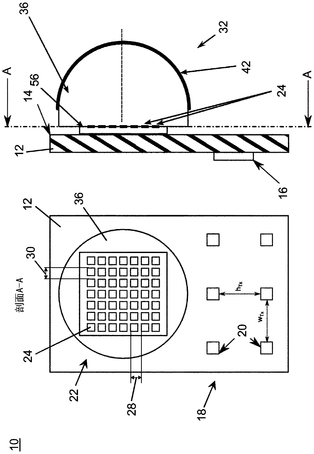
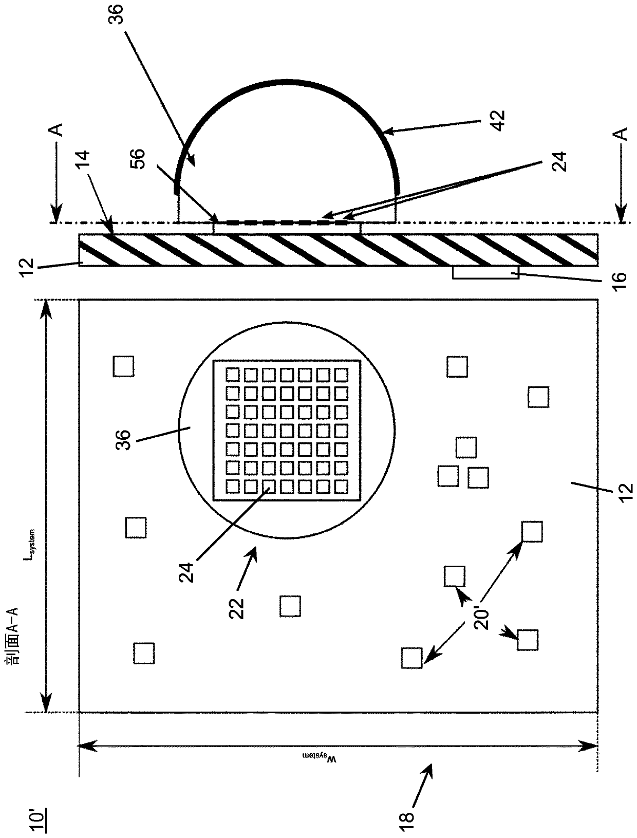
[0080] figure 1A possible embodiment of the radar wave imaging device 10 according to the invention is schematically shown. The radar wave imaging device 10 includes a radar transmitter unit 18 and a radar receiving unit 22 .

[0081] The radar transmitter unit 18 includes a plurality of six radar transmitting antennas 20 regularly arranged in a two-by-three two-dimensional array on the right side portion of the front surface 14 of the substrate 12 and connected to the transmitter circuit 16 . The radar transmitting antenna 20 is directed towards the scene in front of the substrate 12 . The scene may include objects temporarily forming part of the scene, which are to be detected by the radar wave imaging device 10 . The radar transmitting antenna 20 of the radar transmitter unit 18 is configured to transmit radar waves towards the scene. It should be noted that the transmitter circuitry 16 may be arranged below the substrate 12, as figure 1 shown, but it can also be placed...


PUM


Abstract

A radar wave imaging device (10) comprises a radar transmitter unit (18) having at least one radar transmit antenna (20) for transmitting radar waves towards a scene and a radar receiving unit (22) including a plurality of radar receiver members (24) that are arranged as a two-dimensional array, for receiving reflected radar waves. The radar receiving unit (22) includes an imaging radar optics unit (32) for imaging at least a portion of a scene onto at least a portion of the two-dimensional array of radar receiver members (24).The imaging radar optics unit (32) comprises at least a first radarlens (36) that is arranged between the radar receiver members (24) and the scene. The radar receiver members (24) are arranged in direct contact to a surface of the first radar lens (36) that is facing away from the scene.

Description

technical field [0001] In general terms, the present invention relates to a radar wave imaging device that can be used in various applications such as people monitoring, building management and security, and applications on mobile platforms such as small unmanned aerial systems and automobiles, And for sensing applications in the field of Internet of Things. Background technique [0002] The use of radar technology is known in the art of military and avionics. Recently, the development of radar sensors has been concentrated in the automotive field (especially the use of radar technology in the mmWave range between 75 and 81 GHz), for automotive exterior applications such as ADAS (Advanced Driver Assistance Safety is increased by facilitating an optimal reaction of the driver of the vehicle with appropriate warnings, or even by automatically taking over control of the vehicle, eg in collision avoidance systems. [0003] In automotive radar applications, one challenge is to ...

Claims


Application Information

Patent Timeline
Patent Type & Authority Applications(China)
IPC IPC(8): G01S13/89G01S17/89G01S7/03G01S7/481G01S13/32H01Q1/38H01Q1/40H01Q1/52H01Q9/04H01Q13/10H01Q15/02H01Q19/06H01Q21/06H01Q21/24G01S13/42
CPCG01S17/89G01S7/032G01S7/481G01S13/32G01S13/42G01S13/89H01Q1/40H01Q1/523H01Q9/0407H01Q13/10H01Q15/02H01Q19/062H01Q21/065H01Q21/24H01Q1/2283H01Q1/3233H01Q9/045H01Q9/0457H01Q19/09G01S7/027
Inventor T·施皮尔曼N·赫施巴赫
Owner IEE INT ELECTRONICS & ENG SA
Why Eureka
Try Eureka