
Straw returning mini-tiller

A micro-tillage machine and micro-tillage technology, applied in the field of agricultural machinery, can solve the problems of insufficient crushing of corn stalks, unfavorable fertilizer efficiency of straw returning to the field, and incineration of straw, so as to cut off soil capillarity, help soil moisture conservation, reduce Effect of incineration risk

Inactive Publication Date: 2019-08-16
SHANGQIU ACADEMY OF AGRI & FORESTRY
View PDF6 Cites 9 Cited by
  • Summary
  • Abstract
  • Description
  • Claims
  • Application Information

AI Technical Summary

Problems solved by technology

In recent years, with the gradual popularization of straw returning to the field, some new problems have gradually emerged: 1. After wheat, corn and other crops are harvested, there are still high straw stubbles on the ground surface, which brings inconvenience to farmers to cultivate the next crops, especially It is the root stubble of autumn crops, and it is difficult for farmers to deal with it, which increases production costs and labor intensity; 2. At present, most of the straw returned to the field is chopped or crushed and then directly scattered on the ground, and there is a risk of the straw being burned; 3. At present, the general Hard stubble is used for sowing corn, and wheat straw is always covered on the ground. Since wheat straw cannot be fully combined with the soil, the straw rots slowly, which is not conducive to the fertilizer efficiency of straw returning to the field.
4. The crushing degree of corn straw is not fine enough, and it is easy to intertwine, which is more difficult to decompose than wheat straw
The interval between corn harvest and wheat sowing is long. During this period, corn stalks have been idle on the ground, failing to make full use of the time advantage, and let the stalks begin to decompose in advance to reduce the impact of corn stalks on the quality of wheat sowing.

Method used

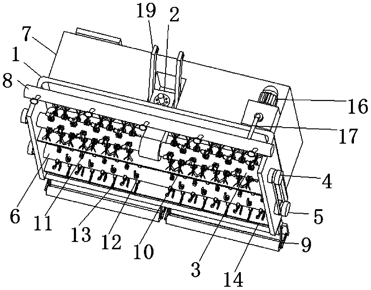
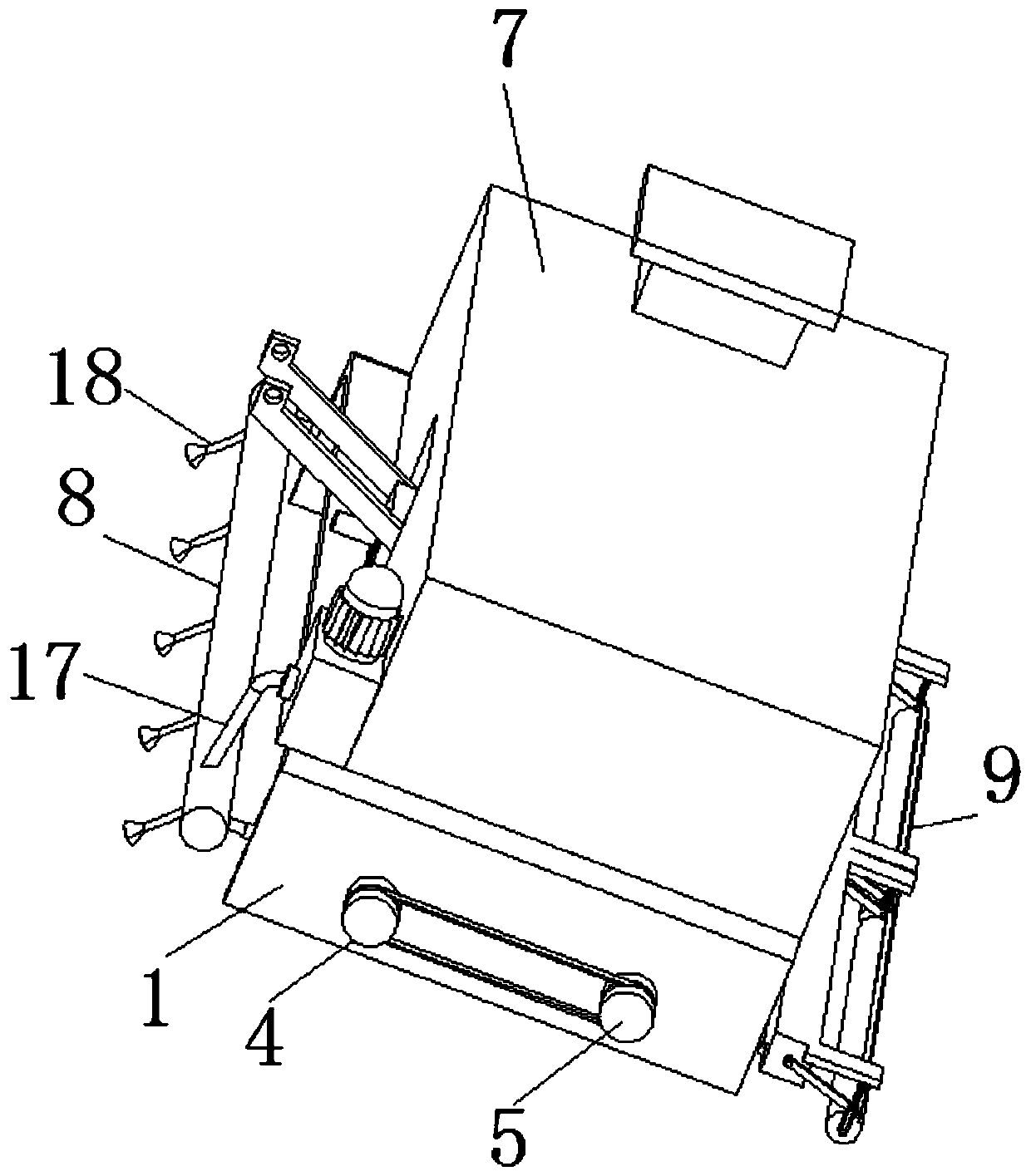
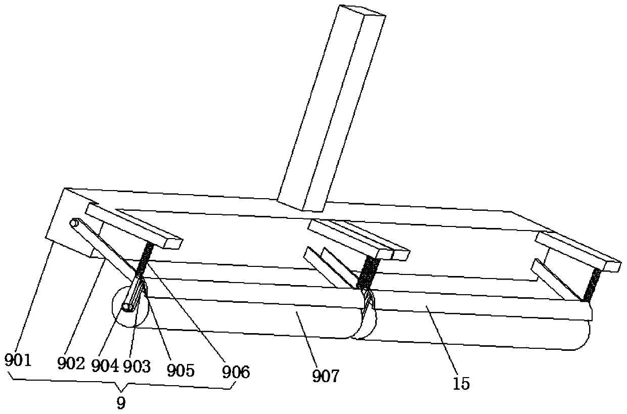

Image

  • Straw returning mini-tiller
  • Straw returning mini-tiller
  • Straw returning mini-tiller

Examples


Embodiment Construction

[0026] The following will clearly and completely describe the technical solutions in the embodiments of the present invention with reference to the accompanying drawings in the embodiments of the present invention. Obviously, the described embodiments are only some, not all, embodiments of the present invention. Based on the embodiments of the present invention, all other embodiments obtained by persons of ordinary skill in the art without making creative efforts belong to the protection scope of the present invention.

[0027] see Figure 1-3 , a micro-tillage machine for returning straw to the field, comprising a micro-tillage crushing shell 1, a gear box 2 is fixedly connected to the middle of the upper surface of the micro-tillage crushing shell 1, and a traction bar 19 is fixedly connected to the left and right sides of the gear box 2. The traction bar The material of 19 is cast steel, and the internal transmission of the gear box 2 is connected with the crushing shaft 3....


PUM


Abstract

The invention discloses a straw returning mini-tiller. The straw returning mini-tiller comprises a mini-tillage smashing shell, wherein a gear case is fixedly connected with the middle of the upper surface of the mini-tillage smashing shell; a smashing shaft is in driving connection with inside of the gear case; one end of the smashing shaft is fixedly connected with a driving wheel; the driving wheel is in driving connection with a driven wheel through a triangular belt; the driven wheel is fixedly connected to one end of a mini-tillage shaft; a mixed liquid storage tank is fixedly connectedwith the upper surface of the mini-tillage smashing shell; a lock cylinder is fixedly connected with one side of the mini-tillage smashing shell, and spraying columns are fixedly connected to inside of the lock cylinder. According to the straw returning mini-tiller, by cooperation of the mixed liquid storage tank, a pressurized water pump and atomizing nozzles, the straw returning mini-tiller canspray a decomposition agent to straw firstly in a using process, so that composting of the crop straw is accelerated, and sufficient mixing of the straw and soil is facilitated at a later stage.

Description

technical field [0001] The invention relates to the technical field of agricultural machinery, in particular to a straw returning tillage machine. Background technique [0002] Straw returning technology is an agricultural technology that chops or crushes crop straws by machinery, and then directly sprinkles them on the ground or applies straws to the soil by mechanical deep plowing or rotary tillage. Straw returning can increase soil fertility, improve soil structure, reduce environmental pollution and so on. In recent years, with the gradual popularization of straw returning to the field, some new problems have gradually emerged: 1. After wheat, corn and other crops are harvested, there are still high straw stubbles on the ground surface, which brings inconvenience to farmers to cultivate the next crops, especially It is the root stubble of autumn crops, and it is difficult for farmers to deal with it, which increases production costs and labor intensity; 2. At present, m...

Claims


Application Information

Patent Timeline
IPC IPC(8): A01B49/04A01B49/02A01D82/00
CPCA01B49/022A01B49/027A01B49/04A01D82/00
Inventor 刘红杰倪永静任德超胡新赵敬领
Owner SHANGQIU ACADEMY OF AGRI & FORESTRY
Learn More