
Pump pipe washing structure and method

A pump tube and pipeline technology, applied in the pump tube cleaning structure and cleaning field, can solve the problems of complex cleaning structure, easy clogging of pump tubes, cumbersome operation, etc., and achieve the effect of improving cleaning quality, improving cleaning efficiency, and simple process

Pending Publication Date: 2019-08-16
HUNAN WUXIN TUNNEL INTELLIGENT EQUIP CO LTD
View PDF0 Cites 0 Cited by
  • Summary
  • Abstract
  • Description
  • Claims
  • Application Information

AI Technical Summary

Problems solved by technology

[0006] The purpose of the present invention is to provide a pump tube cleaning structure and cleaning method to solve the problems that the pump tube is easy to block, the existing cleaning structure is complicated, the operation is cumbersome and time-consuming, etc.

Method used


Image

  • Pump pipe washing structure and method
  • Pump pipe washing structure and method
  • Pump pipe washing structure and method

Examples


Embodiment 1

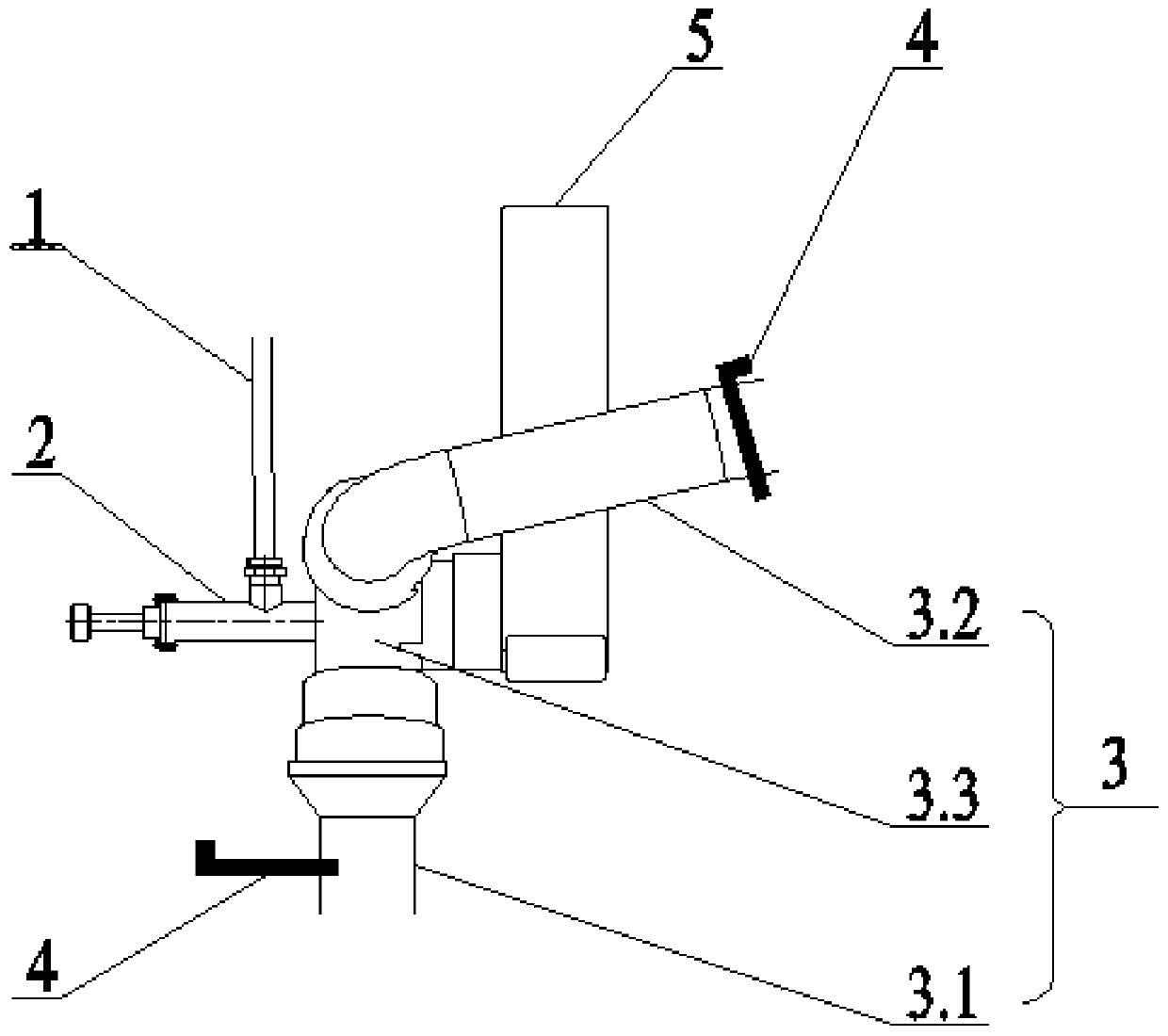
[0030] see Figure 1 ~ Figure 4 , a pump tube cleaning structure and cleaning method, the present embodiment is applied to the pump tube cleaning of the distribution machine on the trolley.

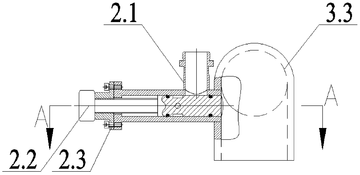
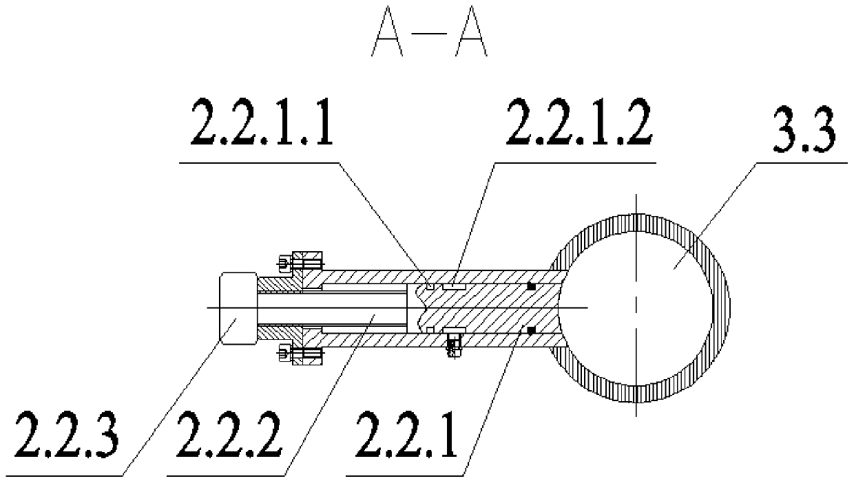
[0031] A pump pipe cleaning structure includes a wind water pipe 1, a valve 2 and a pump pipe 3; the valve 2 includes a valve body 2.1 and a valve core 2.2, and the two interfaces of the valve body 2.1 are respectively connected to the first end of the wind water pipe 1 and the pump pipe 3 The connection holes on the outer wall are connected, and the valve core 2.2 matches the cavity in the valve body 2.1 to control the connection and disconnection of the two interfaces of the valve body 2.1. Such as figure 2 As shown, the direction of the arrow in the figure indicates the screwing direction of the valve core 2.2, and the valve 2 is in the closed state; image 3 As shown, the direction of the arrow in the illustration indicates the direction in which the valve core 2.2 is unscrewed, an...


PUM


Abstract

The invention provides a pump pipe washing structure. The pump pipe washing structure comprises an air and water pipe, a valve and a pump pipe, wherein the valve comprises a valve body and a valve element; two ports of the valve body are correspondingly connected to the first end of the air and water pipe and a connecting hole in the outer wall of the pump pipe; and the valve element fits an emptycavity in the valve body and is used for controlling the connection and disconnection of the two ports of the valve body. The pump pipe washing structure further comprises a pump pipe support for supporting the pump pipe. The invention also provides a washing method for sequentially washing a first pipeline and a second pipeline. The whole pump pipe washing structure is simple; few spare parts are used; the pump pipe is connected to the air and water pipe at an elbow seat through the valve; the valve element is unscrewed, and the valve is opened to pump the pump pipe; the operation is convenient; the problem of blockage of the pump pipe is effectively solved; an air pipe and a water pipe are synchronously connected to the air and water pipe through a T joint, so that water current pressure is increased, and the washing efficiency is improved; the first pipeline and the second pipeline are correspondingly provided with stop valves; a sectional washing method is carried out; water flowsin one direction, so that the pipeline can be quickly cleanly washed; and the washing quality is obviously improved.

Description

technical field [0001] The invention relates to the technical field of engineering construction, in particular to a pump tube cleaning structure and a cleaning method. Background technique [0002] Tunnel lining trolley is a non-standard product specially designed and manufactured for concrete lining of different cross-sectional sizes such as tunnels and culverts. It is characterized by a motor-driven traveling mechanism to drive the trolley to travel, and uses hydraulic cylinders and screw jacks to adjust the formwork in place and close the formwork. , the surface finish of the lining is high, and the lining speed is fast. It has the advantages of low cost, reliable structure, convenient operation, fast lining speed and good tunnel forming surface. [0003] During the lining process of the trolley, the concrete is transported by the pump through the pump pipe, and poured layer by layer and window by window through the distributor. Due to the characteristics of concrete, i...

Claims


Application Information

Patent Timeline
IPC IPC(8): B08B9/032
CPCB08B9/0321
Inventor 王祥军龚俊曾勇宋祖源
Owner HUNAN WUXIN TUNNEL INTELLIGENT EQUIP CO LTD
Features
  • Generate Ideas
  • Intellectual Property
  • Life Sciences
  • Materials
  • Tech Scout
  • Unparalleled Data Quality
  • Higher Quality Content
  • 60% Fewer Hallucinations
Learn More