Steel reinforcement cage machining method and system

A processing system and processing method technology, applied in the direction of wire processing, wire mesh, other household appliances, etc., can solve the problems of large amount of rework, large workload, and inability to guarantee the spacing size, so as to reduce the workload, eliminate rework, and facilitate the construction effect

Pending Publication Date: 2019-08-16
美好建筑装配科技有限公司
View PDF0 Cites 2 Cited by
  • Summary
  • Abstract
  • Description
  • Claims
  • Application Information

AI Technical Summary

Problems solved by technology

The existing steel cage processing is to use a ruler to mark each forming point of each longitudinal bar, then place the stirrups at the forming points, and finally fix the stirrups and longitudinal bars to form. Therefore, the existing steel cage processing Not only is the efficiency low and the workload is heavy, but the key is that the spacing size after forming cannot be guaranteed, which is not conducive to the construction of prefabricated buildings and requires a large amount of rework. Moreover, the existing steel cage processing requires workers to go back and forth between the processing site and the hoop folding machine or Between material storage sites, further reducing efficiency

Method used


Image

  • Steel reinforcement cage machining method and system
  • Steel reinforcement cage machining method and system
  • Steel reinforcement cage machining method and system

Examples


Embodiment Construction

[0022] The present invention will be further described below in conjunction with the accompanying drawings and embodiments.

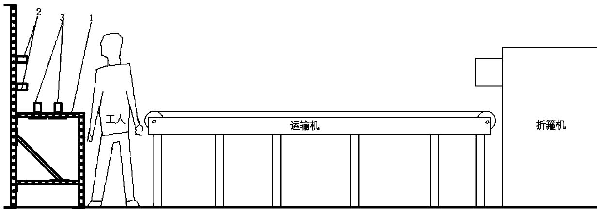
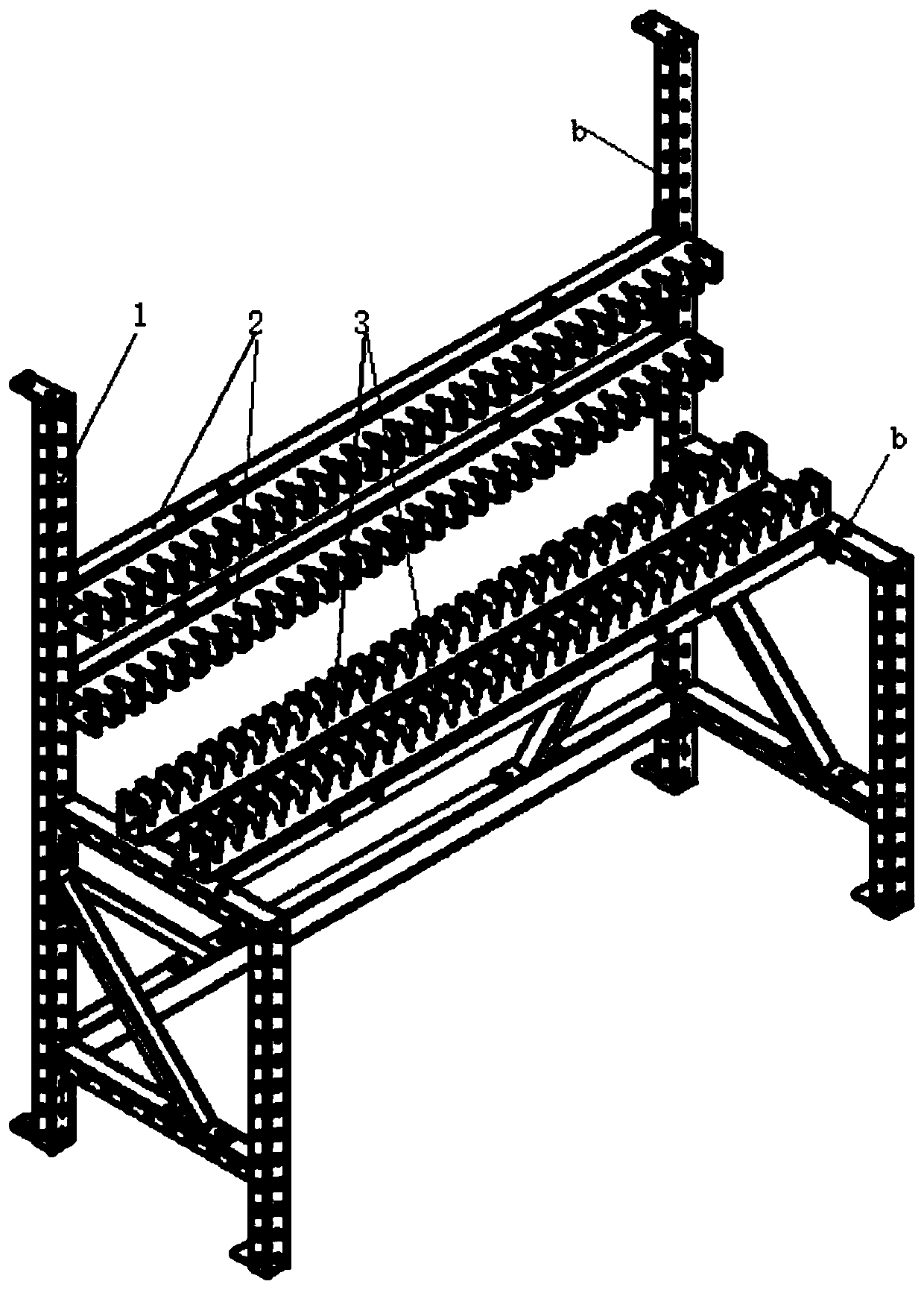
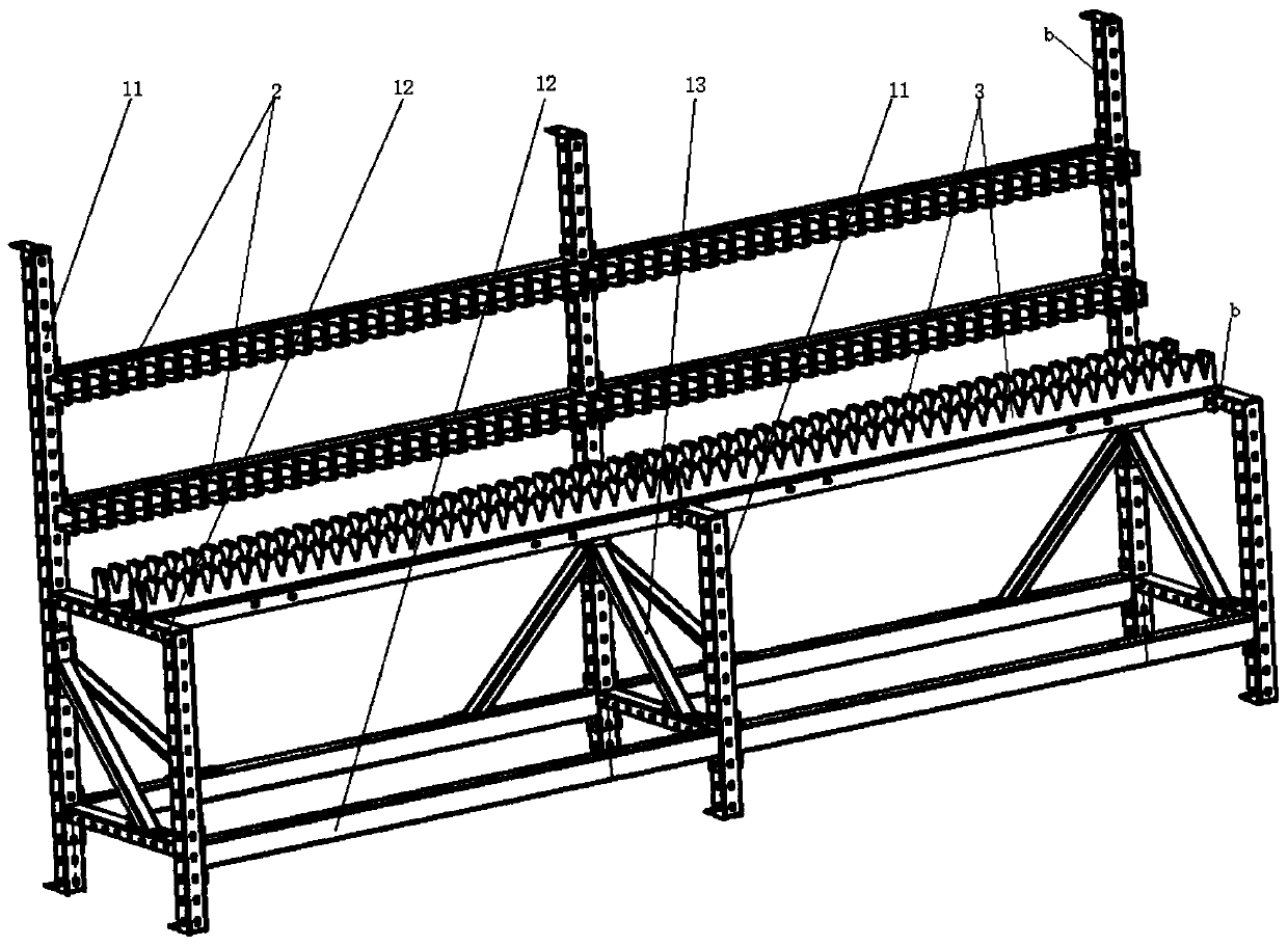
[0023] Such as Figure 1 to Figure 5 Shown, a kind of reinforcement cage processing system comprises hoop folding machine, reinforcement cage sizing tool and transporter; Reinforcement cage sizing tooling comprises frame 1 and spacer bar (2 and 3), and frame 1 top has table top and is vertical to table top The side of the spacer, the distance strips (2 and 3) are arranged on the table and the side, and the front and rear positions on the table are adjustable, and the up and down positions on the side are adjustable, and the distance strips (2 and 3) are evenly distributed with positioning grooves along the length direction a and the spacing of two adjacent positioning slots a is equal to the minimum spacing between the stirrups 5, all spacers (2 and 3) on the frame 1 are parallel and the slots of the positioning slots a are aligned; when the reinforceme...


PUM


Abstract

The invention discloses a steel reinforcement cage machining method and system. A conveyor is arranged between a steel reinforcement cage machining site and a stirrup folding machine, and stirrups made by the stirrup folding machine fall on the conveyor and are directly conveyed to the steel reinforcement cage machining site; and spacing strips are designed, positioning grooves are uniformly distributed in the length direction of the spacing strips, and the distance between every two adjacent positioning grooves is equal to the minimum distance between the stirrups. The multiple parallel spacing strips which are provided with the positioning grooves with aligned notches are arranged, when a steel reinforcement cage is shaped, the bottoms and one sides of the stirrups are respectively clamped in the positioning grooves, the stirrups are simultaneously matched with at least three spacing strips and do not fall vertically, and the distance between the stirrups is controlled by adjusting the stirrups to be placed in the different positioning grooves, the vertical position and the horizontal position and the input number of the spacing strips are adjusted to adapt to the size of the stirrups, when the spacing strips are shorter than longitudinal bars, the size requirements of the longitudinal bars are met by lengthening the spacing strips, and all the stirrups and the longitudinal bars are fixed and formed at a time after being matched. The forming size of a steel reinforcement cage is guaranteed, efficiency is improved, and workload is reduced.

Description

technical field [0001] The invention belongs to the field of prefabricated buildings, and in particular relates to a steel cage processing method and system. Background technique [0002] In prefabricated buildings, prefabricated components are more common. When producing prefabricated components, in order to prevent grout leakage, the distance between the reinforced bars on the side formwork for the ribs is required to be high. The existing steel cage processing is to use a ruler to mark each forming point of each longitudinal bar, then place the stirrups at the forming points, and finally fix the stirrups and longitudinal bars to form. Therefore, the existing steel cage processing Not only is the efficiency low and the workload is heavy, but the key is that the spacing size after forming cannot be guaranteed, which is not conducive to the construction of prefabricated buildings and requires a large amount of rework. Moreover, the existing steel cage processing requires wor...

Claims


Application Information

Patent Timeline
Patent Type & Authority Applications(China)
IPC IPC(8): B21F27/12
CPCB21F27/121
Inventor 涂文磊张少武陈定球
Owner 美好建筑装配科技有限公司
Why Eureka
Try Eureka