

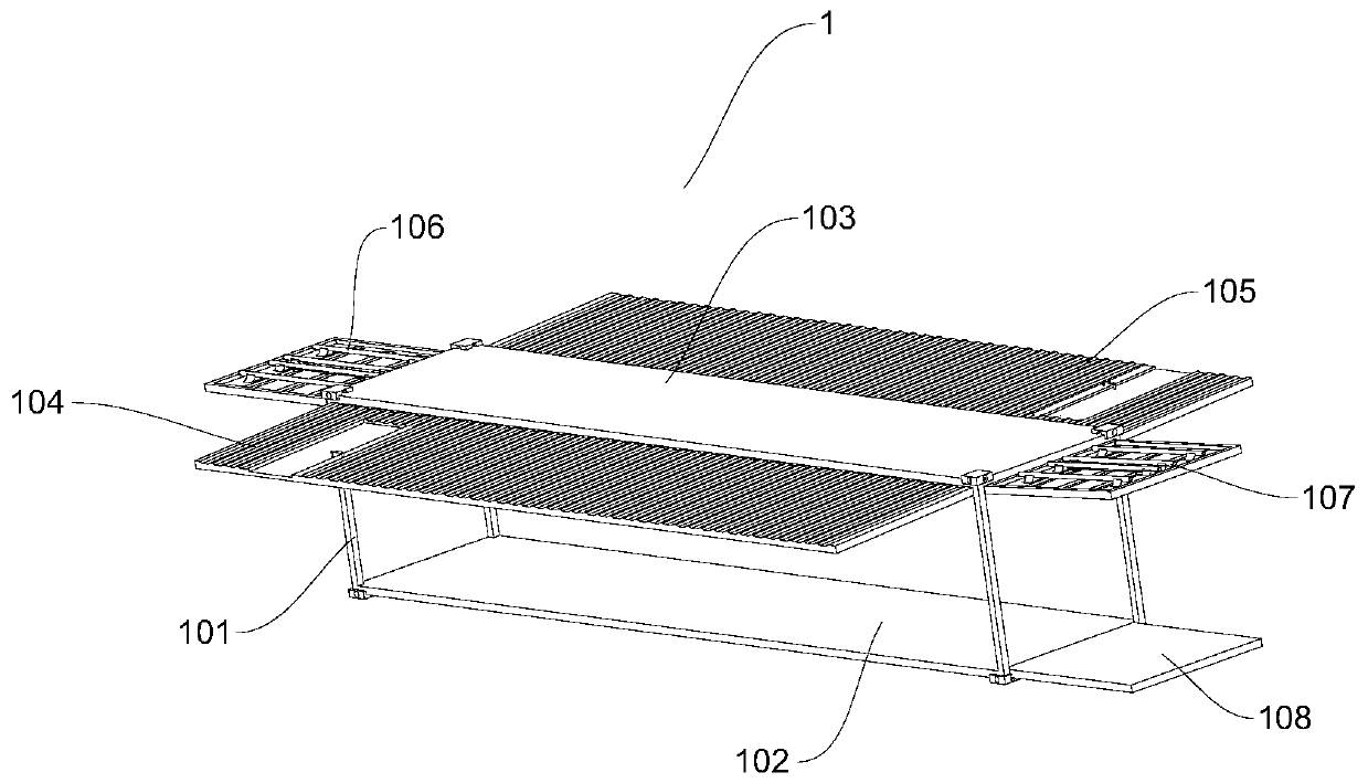
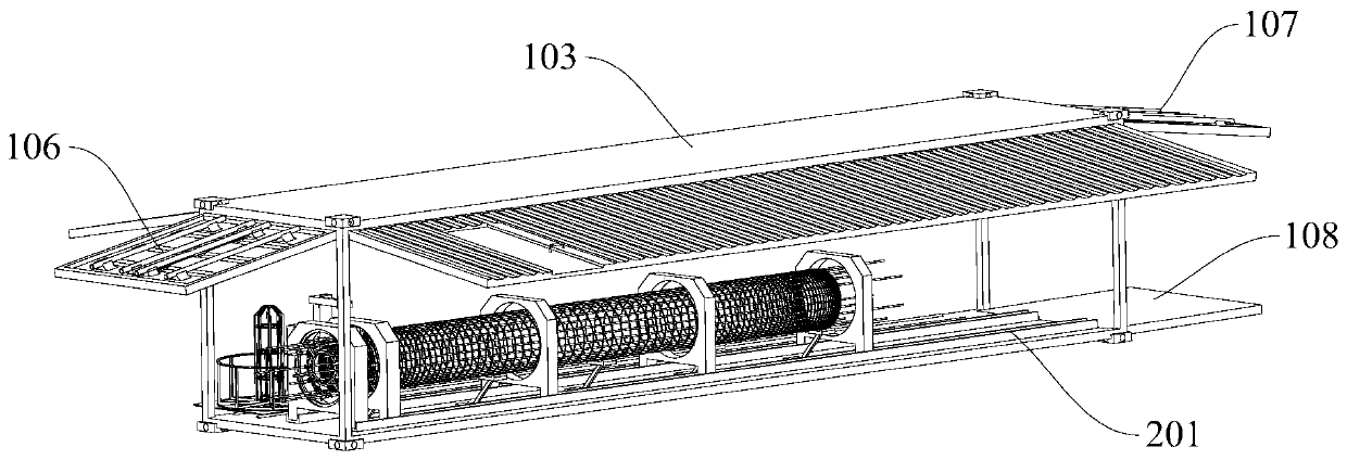
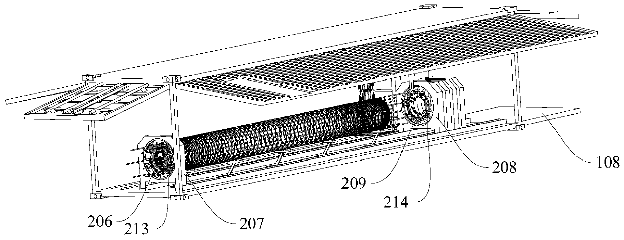
Reinforcement cage manufacturing device
A technology for manufacturing devices and steel cages, which can be applied to online nets, other household appliances, household appliances, etc., can solve problems such as greater impact on project quality, inconvenient transportation of steel cages, and uneven quality, so as to reduce site occupation and protect the interior Mechanism for making cages, saving transportation costs
- Summary
- Abstract
- Description
- Claims
- Application Information
AI Technical Summary
Problems solved by technology
Method used
Image

Examples
Embodiment Construction
[0025] Below, the present invention will be further described in conjunction with the accompanying drawings and specific implementation methods. It should be noted that, under the premise of not conflicting, the various embodiments described below or the technical features can be combined arbitrarily to form new embodiments. .
[0026] In describing the present invention, it is to be understood that the terms "upper", "lower", "front", "rear", "left", "right", "horizontal", "vertical", "top", The orientation or positional relationship indicated by "inner", "outer", etc. is based on the orientation or positional relationship shown in the drawings, and is only for the convenience of describing the present invention and simplifying the description, rather than indicating or implying that the referred device or element must have Certain orientations, constructed and operative in certain orientations, therefore are not to be construed as limitations of the invention. In addition, ...
PUM
 Abstract
Description
Claims
Application Information