An energy-saving thermal deaerator

A thermal deoxygenation, energy-saving technology, applied in the direction of degassed water/sewage treatment, etc., can solve the problems of low heating efficiency, steam energy waste, energy waste, etc., achieve uniform heating, improve overflow efficiency, and high heating efficiency Effect

Active Publication Date: 2021-07-09
湖南达道新能源开发有限公司
View PDF4 Cites 0 Cited by
  • Summary
  • Abstract
  • Description
  • Claims
  • Application Information

AI Technical Summary

Problems solved by technology

[0002] Water often flows in boilers, pipes and heat exchangers of geothermal development equipment, and oxygen, carbon dioxide and other gases are often dissolved in untreated water. This untreated water flows through boilers and pipes, which is easy to damage boilers, The inner wall of pipes and heat exchangers causes corrosion, which affects the service life of geothermal development equipment
[0003] At present, in order to solve this situation, it is usually chosen to install a thermal deaerator at the feed water inlet of the geothermal development equipment. The thermal deaerator is used to remove the dissolved gas in the water first, and then the water is introduced into the geothermal development equipment. Existing thermal deaerators use heating equipment to directly heat the water to be deaerated, and pass steam over the water to be deaerated to take away the oxygen discharged from the water. Most of the energy in it is wasted, and the heating efficiency is very low when heating the water to be deaerated, which causes a waste of energy during deaeration

Method used


Image

  • An energy-saving thermal deaerator
  • An energy-saving thermal deaerator
  • An energy-saving thermal deaerator

Examples


Embodiment Construction

[0022] The present invention will be further described below in conjunction with the accompanying drawings and embodiments.

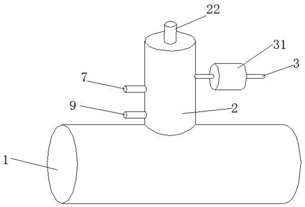
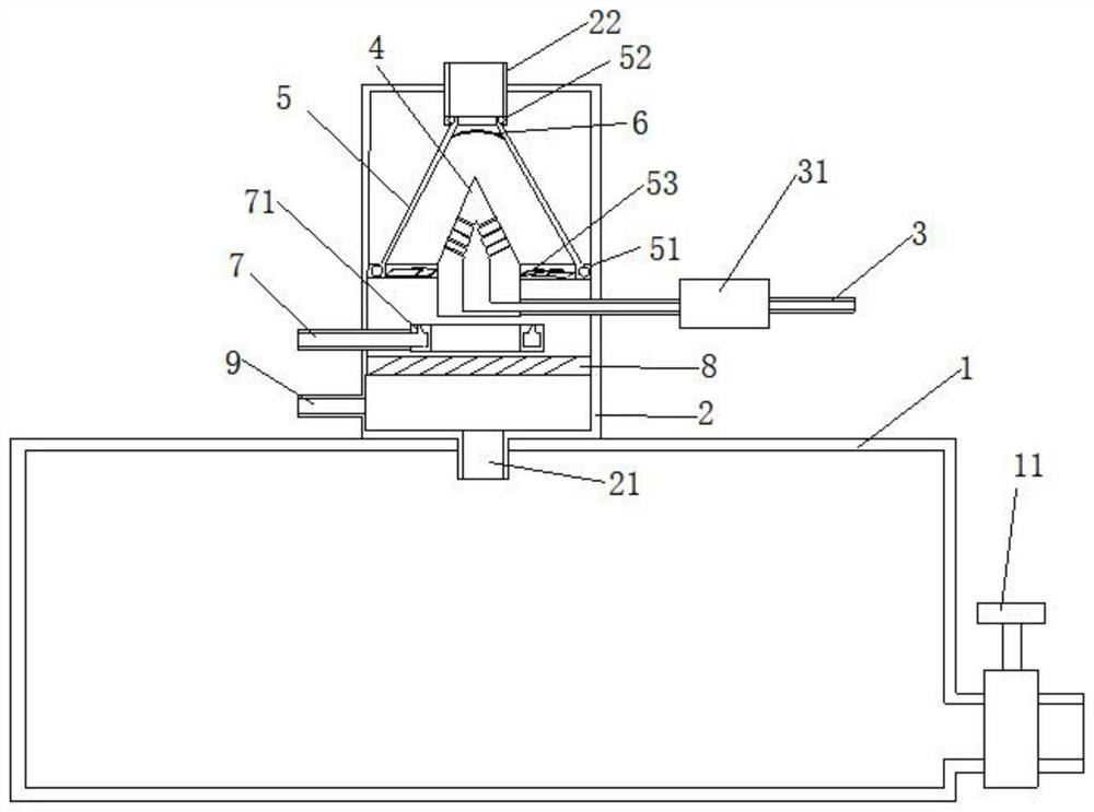
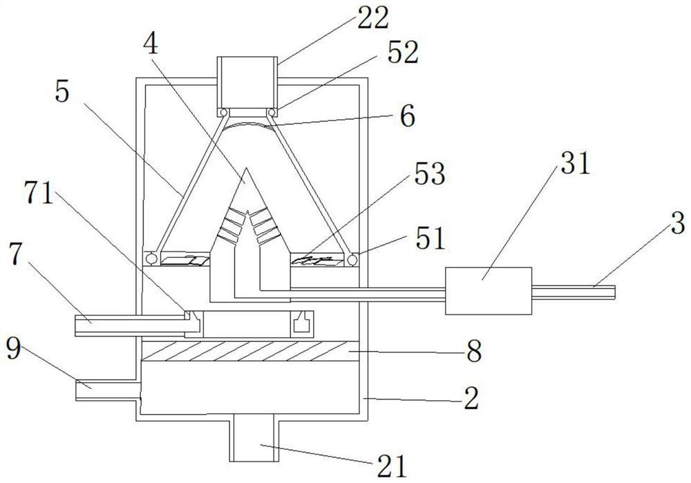
[0023] Please refer to figure 1 , figure 2 as well as image 3 ,in figure 1 A schematic structural view of a preferred embodiment of the energy-saving thermal deaerator provided by the present invention; figure 2 for figure 1 The structural sectional schematic diagram of the energy-saving thermal deaerator shown; image 3 for figure 2 A schematic cross-sectional view of the housing and the internal structure of the housing shown.

[0024] combined reference figure 1 and figure 2 As shown, an energy-saving thermal deaerator includes a cylindrical water tank 1. In the specific implementation process, the bottom surface of the water tank 1 is detachably fixed on the box body of the water tank. It is convenient for maintenance personnel to overhaul the energy-saving thermal deaerator. The top of the water tank 1 is provided with a barometer por...


PUM


Abstract

The energy-saving thermal deaerator provided by the present invention includes: a water tank, a shell, a first steam pipe, a second steam pipe, a water inlet pipe, an annular nozzle, a thermal storage filler net, a nozzle, a water receiving plate, blades and an air outlet pipe. The top of the horizontally placed water tank is provided with the housing, and the side wall of the housing is provided with a first steam pipe, a second steam pipe and a water inlet pipe from bottom to top, and the second steam pipe communicates with the An annular nozzle, the water inlet pipe is connected to the nozzle, the water receiving plate is rotatably connected to the housing, the heat storage packing net is arranged in the housing, and the top of the housing is connected to the water receiving plate. The plate is provided with the outlet pipe. The energy-saving thermal deaerator provided by the invention can efficiently remove dissolved oxygen in water, ensure that the water flowing in the equipment does not contain oxygen, and reduce corrosion to equipment pipelines.

Description

technical field [0001] The invention relates to the field of thermal deaerators, in particular to an energy-saving thermal deaerator. Background technique [0002] Water often flows in boilers, pipes and heat exchangers of geothermal development equipment, and oxygen, carbon dioxide and other gases are often dissolved in untreated water. This untreated water flows through boilers and pipes, which is easy to damage boilers, The inner wall of the pipeline and the heat exchanger causes corrosion, which affects the service life of the geothermal development equipment. [0003] At present, in order to solve this situation, it is usually chosen to install a thermal deaerator at the feed water inlet of the geothermal development equipment. The thermal deaerator is used to remove the dissolved gas in the water first, and then the water is introduced into the geothermal development equipment. Existing thermal deaerators use heating equipment to directly heat the water to be deaerate...

Claims


Application Information

Patent Timeline
Patent Type & Authority Patents(China)
IPC IPC(8): C02F1/20
CPCC02F1/20
Inventor 杨胜伟
Owner 湖南达道新能源开发有限公司
Why Eureka
Try Eureka