Methods and systems for electric turbocharger

A turbocharger, turbine technology, applied in electrical control, combustion engine, engine control, etc., can solve problems such as difficult installation, increase exhaust back pressure, and will not provide other functions

Pending Publication Date: 2019-08-16
FORD GLOBAL TECH LLC
View PDF1 Cites 0 Cited by
  • Summary
  • Abstract
  • Description
  • Claims
  • Application Information

AI Technical Summary

Problems solved by technology

As an example, such valves increase packaging constraints and can be difficult to install due to the compact packaging of modern engine systems
Also, such a valve may not serve a function other than increasing exhaust back pressure

Method used


Image

  • Methods and systems for electric turbocharger
  • Methods and systems for electric turbocharger
  • Methods and systems for electric turbocharger

Examples


Embodiment Construction

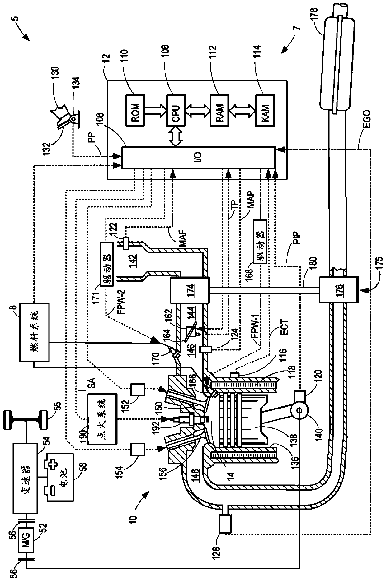
[0013] The following description relates to systems and methods for an electric turbocharger. Electric turbochargers may be included in hybrid vehicles that include engines such as figure 1 of hybrid vehicles.

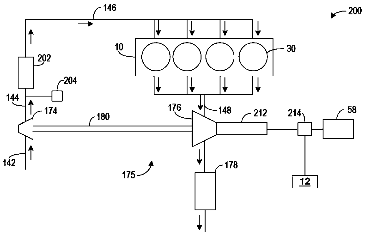
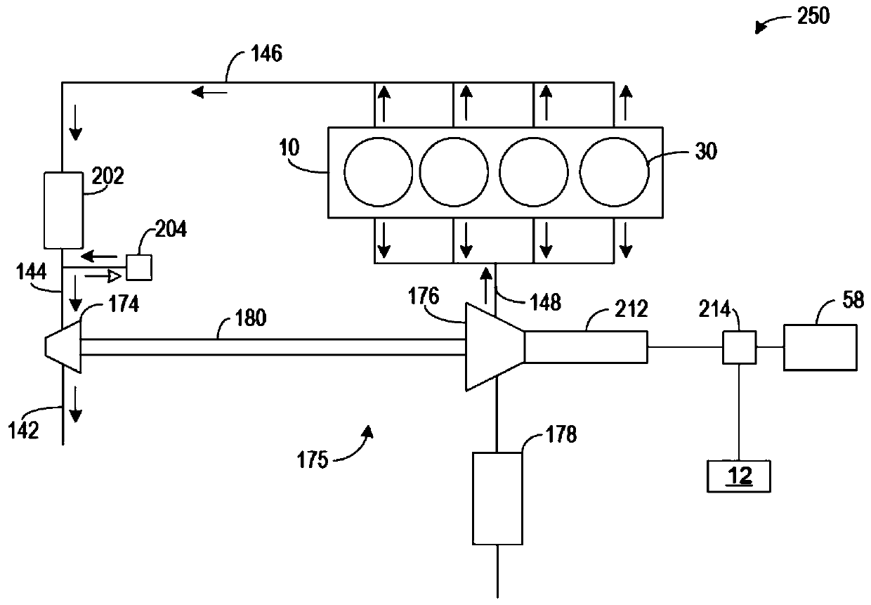
[0014] In some examples, an electric turbocharger includes an electric turbine mechanically coupled to a compressor. Turbine and compressor are shown along the Figure 2A Rotate in the forward direction. When the turbine and compressor rotate in the forward direction, charge air can flow to the engine. Therefore, exhaust backpressure may not increase, and manifold vacuum may not develop. However, when the turbine and compressor rotate in a reverse direction to the forward direction, exhaust backpressure may increase and manifold vacuum may develop, as in Figure 2B shown. Therefore, when the turbine and compressor rotate in opposite directions, charge air may not flow to the engine. The turbine and compressor can rotate in opposite directions during cold starts ...


PUM


Abstract

Methods and systems are provided for an electric turbocharger. In one example, a method rotating a turbine of the electric turbocharger in a reverse direction, the turbine being mechanically coupled to a compressor via a shaft. The rotation of the turbine may be adjusted based on a cold-start and / or engine operating conditions outside of the cold-start.

Description

technical field [0001] This specification generally relates to the use of an electric turbocharger to regulate intake passage pressure and exhaust passage pressure. Background technique [0002] Reducing tailpipe emissions may be a common goal among manufacturers in the automotive industry. As emission standards continue to increase, technology may continue to improve to meet the standards. Exhaust emissions based on current standards may need to be reduced to meet future regulatory requirements. Previous approaches to reducing cold-start emissions have included developing catalysts that heat up and light off quickly at lower temperatures, and optimizing engine cold-start conditions to transfer heat to the catalyst as quickly as possible. However, even with a quick catalyst light-off, there is still a period during cold starts where the catalyst is not hot enough to convert emissions. [0003] Some methods utilize electric heaters to directly heat the catalyst. However, ...

Claims


Application Information

Patent Timeline
IPC IPC(8): F02D9/04F02B37/12
CPCF02D9/04F02B37/12F02B37/10F02B39/10F02D41/064F02D41/0007F02D2200/0406F02D41/08F02D2250/34Y02T10/12
Inventor 张晓刚陈志浩林恩·艾梅·切斯尼帕特里克·马修斯
Owner FORD GLOBAL TECH LLC
Why Eureka
Try Eureka