
Mechanical arm hydraulic system

A hydraulic system and hydraulic lock technology, which is applied in the hydraulic system field of the mechanical arm, can solve the problems of solenoid valve control, falling of heavy objects in the mechanical claw, and failure to maintain the pressure of the oil cylinder, etc.

Inactive Publication Date: 2019-08-16
武汉智仁传控技术有限公司
View PDF6 Cites 9 Cited by
  • Summary
  • Abstract
  • Description
  • Claims
  • Application Information

AI Technical Summary

Problems solved by technology

[0004] In case of unexpected power failure, the solenoid valve will not be able to control the cylinder, and the pressure of the cylinder will not be maintained, causing the heavy objects grabbed by the mechanical claws to fall

Method used


Image

  • Mechanical arm hydraulic system
  • Mechanical arm hydraulic system

Examples


Embodiment Construction

[0023] In order to make the object, technical solution and advantages of the present invention clearer, the implementation manner of the present invention will be further described in detail below in conjunction with the accompanying drawings.

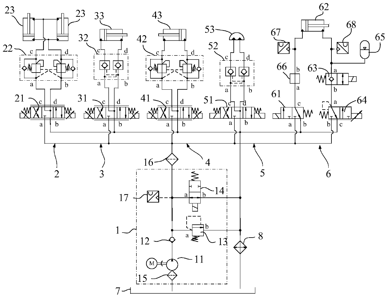
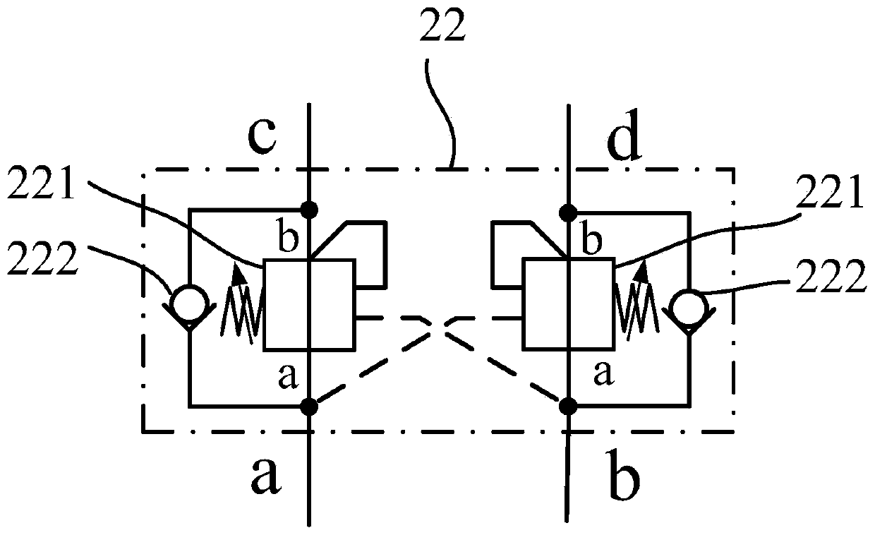
[0024] An embodiment of the present invention provides a hydraulic system of a mechanical arm, such as figure 1 As shown, the hydraulic system includes an energy supply module 1, a shoulder joint module 2, an elbow joint module 3, a wrist joint pitch module 4, a wrist joint swing module 5 and a claw module 6. The energy supply module 1 is connected to the shoulder joint module 2, The elbow joint module 3, the wrist joint pitch module 4, the wrist joint swing module 5 and the gripper module 6 are in communication, and the gripper module 6 includes a first control valve 61, a gripper cylinder 62, an electromagnetic stop valve 63 and a second control valve 64, The oil port a of the first control valve 61 communicates with the oil supply p...


PUM


Abstract

The invention discloses a mechanical arm hydraulic system, and belongs to the field of mechanical devices. The hydraulic system comprises an energy supply module, a shoulder joint module, an elbow joint module, a wrist joint pitching module, a wrist joint swinging module and a paw module; the paw module comprises a first control valve, a paw oil cylinder, an electromagnetic stop valve and a secondcontrol valve; the a oil port of the first control valve communicates with the oil supply port of the energy supply module; the b oil port of the first control valve communicates with an oil tank ofthe hydraulic system; the c oil port of the first control valve communicates with a rodless cavity of the paw oil cylinder; a rod cavity of the paw oil cylinder communicates with the a oil port of theelectromagnetic stop valve; the b oil port of the electromagnetic stop valve communicates with the a oil port of the second control valve; the b oil port of the second control valve communicates withthe oil supply port of the energy supply module; and the c oil port of the second control valve communicates with the oil tank. The reliability of a mechanical arm can be improved.

Description

technical field [0001] The invention belongs to the field of mechanical devices, in particular to a hydraulic system of a mechanical arm. Background technique [0002] The robotic gripper is an important part of the robotic arm, which is controlled by a hydraulic system. The hydraulic system usually includes an oil cylinder and a solenoid valve. The solenoid valve controls the expansion and contraction of the piston rod of the oil cylinder to realize the tightening and loosening of the claws. [0003] In the process of realizing the present invention, the inventor finds that there are at least the following problems in the prior art: [0004] In case of unexpected power failure, the solenoid valve will not be able to control the oil cylinder, and the pressure of the oil cylinder will not be maintained, causing the heavy objects grabbed by the mechanical claws to fall. Contents of the invention [0005] The embodiment of the present invention provides a hydraulic system o...

Claims


Application Information

Patent Timeline
Patent Type & Authority Applications(China)
IPC IPC(8): F15B1/02F15B11/16F15B13/01F15B13/06F15B21/041F15B21/0423B25J9/14B25J15/02
CPCB25J9/14B25J15/02F15B1/02F15B11/16F15B13/01F15B13/06F15B21/041F15B2211/205F15B2211/212F15B2211/615F15B2211/62F15B2211/71F15B21/0423
Inventor 张范蒙胡小东朱显宇
Owner 武汉智仁传控技术有限公司
Learn More