Power supply safety protection system

A technology of safety protection and power supply, which is applied in the direction of emergency power supply arrangements, electrical components, circuit devices, etc., can solve the problems of time interval and power supply, and achieve the effect of solving power failure and avoiding wrong switching

Active Publication Date: 2019-08-16
济南汇恒电气有限公司
View PDF3 Cites 7 Cited by
  • Summary
  • Abstract
  • Description
  • Claims
  • Application Information

AI Technical Summary

Problems solved by technology

[0005] In view of the above situation, in order to overcome the defects of the prior art, the purpose of the present invention is to provide a power supply safety protection system, which has the characteristics of ingenious conception and humanized design, and effectively solves the problem of time intervals during power switching and load short-circuits. power problem

Method used


Image

  • Power supply safety protection system
  • Power supply safety protection system
  • Power supply safety protection system

Examples


Embodiment 1

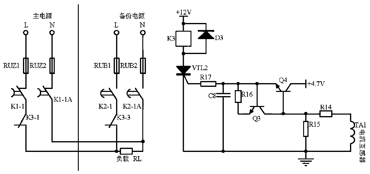
[0018] Embodiment 1, a power supply safety protection system includes a main power supply, a backup power supply, and a load. The main power supply and the backup power supply are redundant power supplies. When the main power supply fails, the backup power supply supplies power to the load. A fault prediction circuit, Charge storage pump circuit, short circuit judgment circuit;

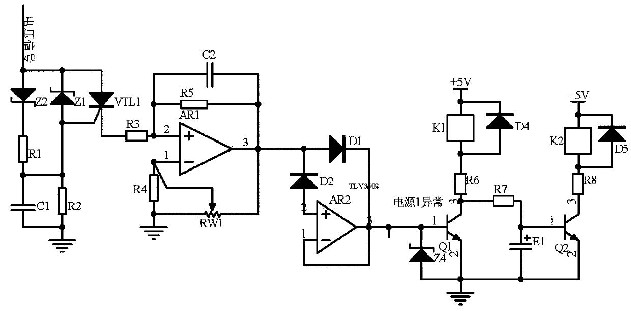
[0019] The fault prediction circuit receives the voltage signal of the main power supply phase line L induced by the voltage transformer, and when the allowable deviation exceeds ±7%, the thyristor VTL1 is triggered to conduct, and the voltage signal enters the integral circuit with the operational amplifier AR1 as the core to calculate the voltage change rate , when the voltage change rate increases positively and is higher than the voltage corresponding to the allowable deviation ±9%, it is predicted to be a fault, the transistor Q1 is turned on, and all the way triggers the coil of the relay K1 to b...

Embodiment 2

[0022] Embodiment 2, on the basis of Embodiment 1, the short-circuit determination circuit detects the current flowing through the load through the current transformer TA1, and converts it into a voltage through the resistor R14, which is higher than the threshold voltage corresponding to the short-circuit current (that is, the normal operation of the equipment 7 times the rated current), the triode Q3 and Q4 form a composite tube to conduct, and after the voltage is delayed by the resistor R17 and the capacitor C8, the thyristor VTL2 is triggered to conduct, the coil of the relay K3 is energized, and the normally closed contacts K3-1, K3-2 are all disconnected, so that the main power supply, backup power supply, and load storage pump circuit do not supply power to the load, including the current transformer TA1, the upper end of the current transformer TA1 is connected to one end of the resistor R14, and the other end of the resistor R14 is connected to the resistor One end of...

Embodiment 3

[0023]Embodiment three, on the basis of embodiment one, the fault prediction circuit receives the 0-5V voltage signal of the main power supply phase line L induced by the voltage transformer (a voltage transformer with a transformation ratio of 100 / 2 can be used for induction) , When the allowable deviation is ±7%, that is, when the power supply is lower than 204.6 or higher than 235.4, the voltage regulator tube Z1 or Z2 reverses breakdown, the thyristor VTL1 triggers conduction, and the voltage signal enters the operational amplifier AR1, resistor R3-resistor R5 , Potentiometer RW1, capacitor C2 composed of integral amplification circuit integration, calculate the voltage signal corresponding to the output voltage change rate for a certain period of time, the integral time constant is determined by the value of resistor R3, capacitor C2, in order to avoid the operational amplifier AR1 offset setting feedback Resistor R5, potentiometer RW1 feedback potentiometer, used to contr...


PUM


Abstract

The invention discloses a power supply safety protection system. A fault prediction circuit receives a voltage signal of a main power supply phase line L induced by a voltage transformer, a voltage change rate is calculated when the voltage signal exceeds an allowable deviation for 7%, and a failure is predicted when the voltage signal exceeds an allowable deviation for 9%. At that time, in one path, a normally closed switch K1-1 is controlled to be delayed and switched off, a normally closed switch K1-2 is switched on, a main power supply is delayed and switched off, and a charge storage pumpcircuit temporarily supplies power to a load. In another path, a normally closed switch K2-1 is controlled to be delayed and switched off, and a backup power supply is started. When the fault prediction is normal, the charge storage pump circuit allows the charging of an energy storage circuit and electric energy storage, the voltage is transformed into AC220V by a boosting circuit, and the loadis powered when the failure of the main power supply is predicted. A short circuit determination circuit detects current flowing through the load through a current transformer, when short circuit occurs, transistors Q3 and Q4 form a composite tube for conduction, a relay K3 coil is energized, both normally closed contacts K3-1 and K3-2 are disconnected, and the main power supply, the backup powersupply and the charge storage pump circuit do not supply power to the load.

Description

technical field [0001] The invention relates to the technical field of power supply control, in particular to a power supply safety protection system. Background technique [0002] For some systems that require long-term uninterrupted operation and high reliability, such as base station communication equipment, monitoring equipment, servers, etc., high reliability power supply is often required. Redundant power supply design is a key part of it. Generally, two redundant power supplies are configured. Or two or more power supplies, when one power supply fails, other power supplies can be put into operation immediately without interrupting the normal operation of the equipment. [0003] Redundant power supply is divided into three types, redundant cold backup (one of the power supplies is powered normally, when it fails, the backup power supply immediately starts to work), parallel current sharing N+1 backup (each power supply is connected in parallel through OR gate diodes) ...

Claims


Application Information

Patent Timeline
Patent Type & Authority Applications(China)
IPC IPC(8): H02J9/06
CPCH02J9/061H02J9/068
Inventor 雷钢焦合军李红丽孙建延陈俊民
Owner 济南汇恒电气有限公司
Why Eureka
Try Eureka