
Piezoelectric inchworm rotating motor

A technology of rotating electric machines and electric inchworms, which is applied in the direction of piezoelectric effect/electrostrictive or magnetostrictive motors, generators/motors, electrical components, etc., which can solve the problem of reduced motion stability, motors that cannot be self-locked, and cannot output Shaft clamping or release, etc., to achieve the effect of eliminating the assembly and adjustment process, integrating the driving mechanism, and being easy to assemble and adjust

Active Publication Date: 2019-08-16
NINGBO UNIV
View PDF4 Cites 4 Cited by
  • Summary
  • Abstract
  • Description
  • Claims
  • Application Information

AI Technical Summary

Problems solved by technology

[0005] 3) The output displacement of the clamping unit is small, and the output shaft cannot be fully clamped or released. If the output shaft cannot be fully clamped, the clamping force it receives will be reduced, and the motion stability will be reduced; the output shaft If it cannot be fully released, it will cause serious friction and wear and reduce the life of the motor;
[0006] 4) The motor cannot be self-locked (that is, it cannot be clamped with power off), that is, when the motor is not working, the output shaft cannot be clamped by the clamp unit;
[0007] 5) The output shaft only rotates one step in one drive voltage cycle (ie one beat), and the motor moves slowly

Method used


Image

  • Piezoelectric inchworm rotating motor
  • Piezoelectric inchworm rotating motor
  • Piezoelectric inchworm rotating motor

Examples


Embodiment Construction

[0046] Embodiments of the present invention will be further described in detail below in conjunction with the accompanying drawings.

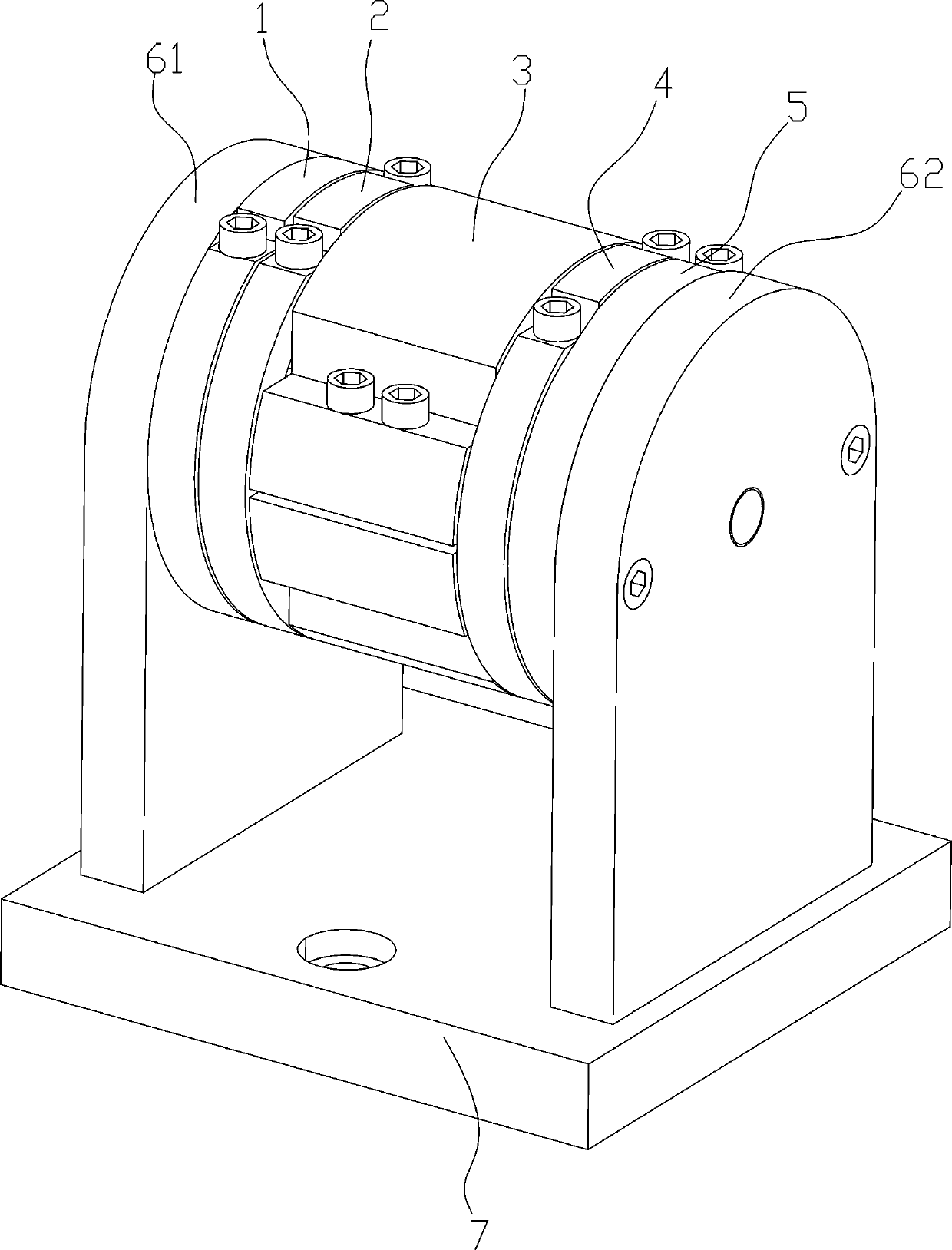
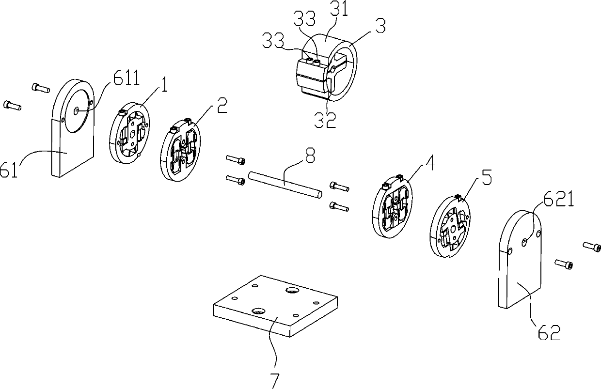
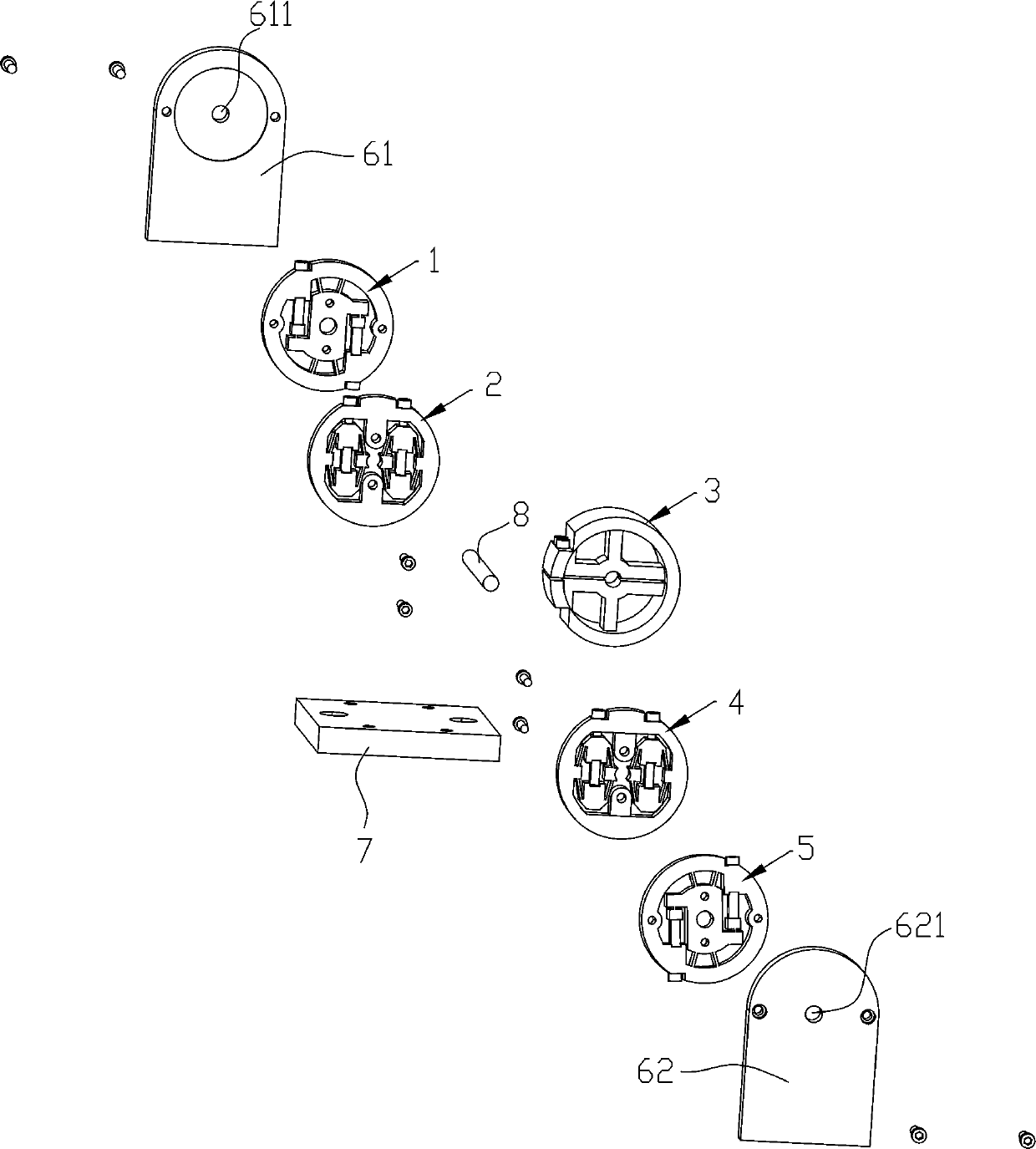
[0047] Figure 1 to Figure 7It is a structural schematic diagram of the present invention, and the reference signs therein are: first driving part 1, first rigid ring 11, first positioning groove 111, first rigid rotating body 12, first shaft hole 121, first driving pressure Electric actuator 13, first rigid floating block 14, first flexible hinge 15, first preload screw 16, third flexible thin plate 17, first clamping part 2, third rigid ring 21, first rigid body 22, The second rigid body 23, the third rigid body 24, the fourth rigid body 25, the first arc surface 251, the first flexible thin plate 26, the first release piezoelectric actuator 27, the fourth pre-tightening screw 28, the first Bridge type amplification mechanism 29, sleeve 3, first split 31, second split 32, third preload screw 33, second clamping part 4, fourth rigid ring 41, ...


PUM


Abstract

The invention discloses a piezoelectric inchworm rotating motor which comprises a bottom plate for fixation, a first end cover and a second end cover vertically connected to the bottom plate, an output shaft disposed between the first end cover and the second end cover, and a sleeve fixed to the output shaft, wherein one side of the sleeve is provided with a first clamping portion and a first driving portion, and the other side is provided with a second clamping portion and a second driving portion. The sleeve is a connector for external output and is fixed to the output shaft to rotate synchronously with the output shaft. The first driving portion is internally provided with a first rigid rotating body that is rotated forward after being energized, the second driving portion is internallyprovided with a second rigid rotating body that is rotated reversely after being energized, the first clamping portion is rotated synchronously with the first rigid rotating body, and the second clamping portion is rotated synchronously with the second rigid rotating body. The piezoelectric inchworm rotating motor has a simple structure, the sufficient clamping and release and power-off clampingcan be achieved, and the 'single beat two steps' rotation of the output shaft can be achieved by the timing control of the first clamping portion, the second clamping portion, the first driving portion and the second driving portion.

Description

technical field [0001] The invention belongs to the field of nano-positioning technology, relates to a precision rotary driver with large rotation angle stroke and high rotation angle resolution, and in particular to a piezoelectric inchworm rotary motor. Background technique [0002] Piezoelectric inchworm rotary motor is a precision rotary actuator that can not only realize 360º rotation, but also achieve high angular resolution at the arc-second level. Based on the principle of inchworm crawling in bionics, it continuously accumulates the small displacement of the piezoelectric actuator to form a continuous large stroke angle displacement. Compared with the electromagnetic rotating motor, the piezoelectric inchworm rotating motor has the advantages of no magnetic field and easy control; compared with the ultrasonic resonance type, inertial drive type piezoelectric rotating motor, it has the advantages of large output force, high power density, stable positioning, and no f...

Claims


Application Information

Patent Timeline
IPC IPC(8): H02N2/02H02N2/04
CPCH02N2/023H02N2/046
Inventor 崔玉国宋林李锦棒应志奇周鹏飞惠相君
Owner NINGBO UNIV
Learn More