
Motor rotor temperature estimation method and device and controller

A technology of motor rotor and shutdown temperature, applied in the direction of motor control, control system, electrical components, etc., can solve the problems of signal acquisition difficulty, motor output torque drop, high cost, etc., to reduce cost, improve reliability, and reduce complexity Effect

Inactive Publication Date: 2019-08-16
ZHEJIANG GEELY HLDG GRP CO LTD +1
View PDF4 Cites 13 Cited by
  • Summary
  • Abstract
  • Description
  • Claims
  • Application Information

AI Technical Summary

Problems solved by technology

Permanent magnet synchronous motors for automobiles need to estimate the output torque of the motor, but the permanent magnet rotor flux ψ f The size of the motor has a great relationship with the temperature. If the temperature of the motor rotor is not known, the estimated value of the motor output torque will be inaccurate.
[0005] During the control process of the permanent magnet synchronous motor, the magnetic flux ψ of the permanent magnet f It will change with the change of temperature. When the permanent magnet temperature is too high, the magnetic flux ψ f It will be lower than normal temperature. Under the condition of constant stator current, the motor output torque T e ability will decrease
Moreover, when the temperature of the permanent magnet exceeds a certain critical high temperature, the permanent magnet will experience irreversible demagnetization, which will lead to damage to the permanent magnet synchronous motor. Therefore, it is very necessary to monitor the temperature of the permanent magnet and carry out certain control way to protect the permanent magnet from overheating
[0006] Since the permanent magnet of the motor is a rotating part, the temperature sensor installed on the rotor of the moving part has a complex structure and difficult signal acquisition. Therefore, the method of using a temperature sensor to monitor the permanent magnet is not only costly, but also prone to system failures

Method used


Image

  • Motor rotor temperature estimation method and device and controller
  • Motor rotor temperature estimation method and device and controller
  • Motor rotor temperature estimation method and device and controller

Examples


Embodiment 1

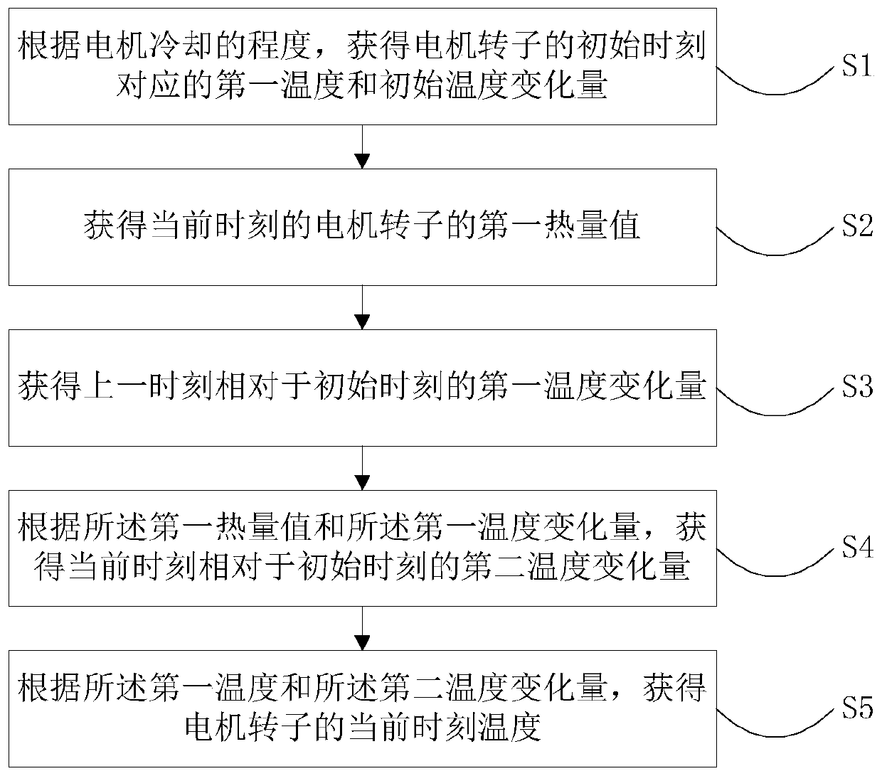
[0066] An embodiment of the present invention provides a motor rotor temperature estimation method, such as figure 1 As shown, the method includes:

[0067] S1. Obtain the first temperature corresponding to the initial moment of the motor rotor and the initial temperature change according to the cooling degree of the motor;

[0068] S2. Obtain the first calorific value of the motor rotor at the current moment;

[0069] S3. Obtain the first temperature change amount at the previous moment relative to the initial moment;

[0070] S4. According to the first calorific value and the first temperature change, obtain a second temperature change at the current moment relative to the initial moment;

[0071] S5. Obtain the current moment temperature of the motor rotor according to the first temperature and the second temperature variation.

[0072] Further, according to the cooling degree of the motor, obtaining the first temperature corresponding to the initial moment of the motor ...

Embodiment 2

[0162] A feasible embodiment of the present invention provides a device for estimating the rotor temperature of a motor. Specifically, such as Figure 6 As shown, the device includes: an initial temperature obtaining module 201, a heat value obtaining module 202, a temperature variation obtaining module 203 and a current moment temperature obtaining module 204;

[0163] The initial temperature obtaining module 201 is used to obtain the first temperature at the initial moment and the initial temperature variation according to the cooling degree of the motor;

[0164] The calorific value obtaining module 202 is used to obtain the first calorific value of the motor rotor at the current moment;

[0165] The temperature change obtaining module 203 is used to obtain the first temperature change at the previous time relative to the initial time, and obtain the second temperature at the current time relative to the initial time according to the first calorific value and the first tem...

Embodiment 3

[0223] Another feasible embodiment of the present invention provides a controller. The controller includes the aforementioned device for estimating the rotor temperature of a motor. The controller is used to protect the motor from overheating when it is judged that the current temperature of the rotor of the motor exceeds the set value, such as reducing the output power of the motor, reducing the output current of the motor, etc., to prolong the service life of the motor.

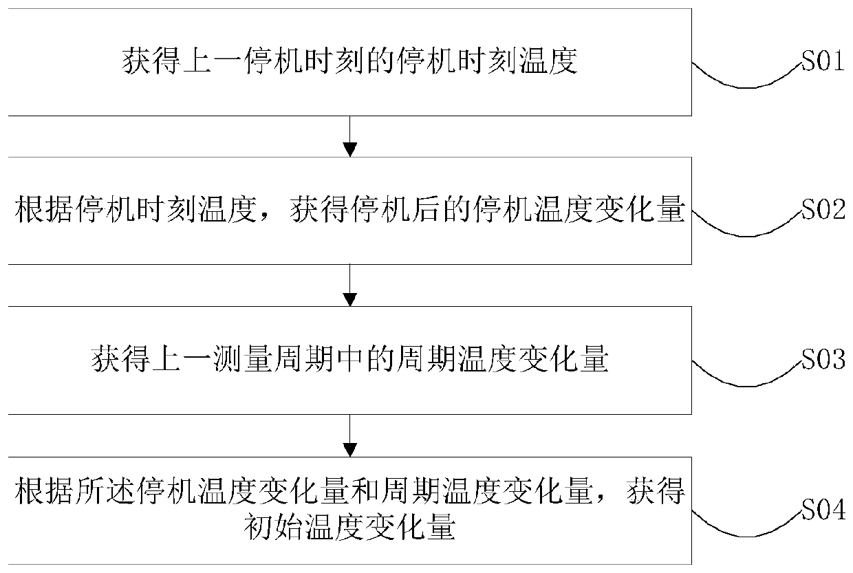
[0224] The storage unit of the controller can also store various state values, and store the temperature change ΔT at the time of shutdown stopn , the temperature T at the time of shutdown stopn and stop time t stopn , used to calculate the initial temperature change in the next temperature estimation.


PUM


Abstract

The invention relates to the technical field of motors, and presents a motor rotor temperature estimation method and device and a controller. The method includes the following steps: establishing a heat generation model to obtain the amount of heat generated; establishing a heat dissipation model to obtain the amount of heat dissipated; establishing a temperature rise model; obtaining the temperature variation at the current time relative to the initial time according to the amount of heat generated, the amount of heat dissipated and the initial temperature variation; and estimating the temperature of the motor according to the temperature variation at the current time relative to the initial time and the initial temperature. The method of estimating the temperature of the motor rotor through the heat generation and heat dissipation models of the motor accords with the law of thermophysics, and the temperature of the motor rotor can be accurately estimated under the condition of accurately calibrating the influence factors of heat generation and heat dissipation of the motor. At the same time, the method does not need a temperature sensor arranged in the motor, the complexity of the system is reduced, the cost is lowered, and the reliability of the system is improved.

Description

technical field [0001] The invention relates to the technical field of motors, in particular to a method, device and controller for estimating the temperature of a motor rotor. Background technique [0002] The permanent magnet synchronous motor generally consists of the following parts: the motor stator winding part, the permanent magnet rotor of the motor, the motor controller and the motor cooling system. According to the torque output formula of permanent magnet synchronous motor: [0003] [0004] where T e Refers to the output torque, p refers to the number of pole pairs of the motor, ψ f is the magnetic flux of the permanent magnet rotor, L d and i d is the d-axis inductance and current of the three-phase stator winding, L q and i q is the q-axis inductance and current of the three-phase stator winding. Permanent magnet synchronous motors for automobiles need to estimate the output torque of the motor, but the permanent magnet rotor flux ψ f The size of the...

Claims


Application Information

Patent Timeline
IPC IPC(8): H02P29/66
CPCH02P29/662
Inventor 陈刚
Owner ZHEJIANG GEELY HLDG GRP CO LTD
Learn More