Coating equipment for thermal spraying

A coating equipment, thermal spraying technology, applied in the direction of spraying device, non-rotation vibration suppression, etc., can solve the problems of inconvenience, the workpiece placement table cannot be rotated, affecting the spraying effect, etc., and achieve the effect of strong practicability

Inactive Publication Date: 2019-08-20
江苏纵湖涂装设备产业研究院有限公司
View PDF1 Cites 3 Cited by
  • Summary
  • Abstract
  • Description
  • Claims
  • Application Information

AI Technical Summary

Problems solved by technology

[0003] The prior art has the following problems: 1. The workpiece clamping device to be sprayed in the existing thermal spraying coating equipment (reference document: CN201820659414.9) needs to be manually adjusted and fixed, which is very inconvenient; 2. The existing thermal spraying The workpiece placement table of the spray coating equipment cannot be rotated, which will lead to uneven spraying of the workpiece to be sprayed and affect the spraying effect

Method used


Image

  • Coating equipment for thermal spraying
  • Coating equipment for thermal spraying

Examples


Embodiment Construction

[0017] The following will clearly and completely describe the technical solutions in the embodiments of the present invention with reference to the accompanying drawings in the embodiments of the present invention. Obviously, the described embodiments are only some, not all, embodiments of the present invention. Based on the embodiments of the present invention, all other embodiments obtained by persons of ordinary skill in the art without making creative efforts belong to the protection scope of the present invention.

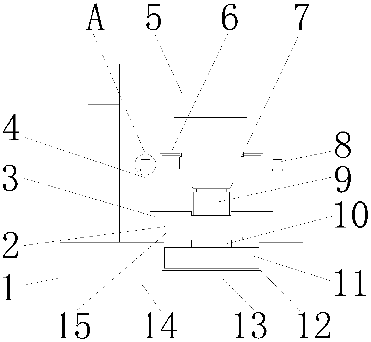
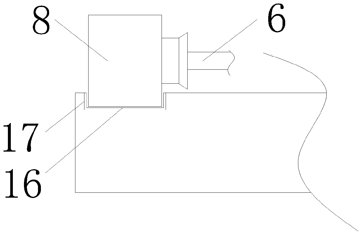
[0018] see Figure 1-2 , the present invention provides the following technical solutions: a thermal spray coating equipment, comprising a box 1, the bottom of the box 1 is provided with a base 14, the inside of the base 14 is provided with a first groove 12, the first groove 12 The inner wall is provided with a first rubber gasket 13, a rotating motor 11 is arranged above the first rubber gasket 13, a rotating shaft 10 is arranged above the rotating motor 11,...


PUM


Abstract

The invention discloses coating equipment for thermal spraying. The coating equipment comprises a box body, wherein a base is arranged at the bottom of the box body, a first groove is formed in the base, a first rubber gasket is arranged on the inner side wall of the first groove, a rotating motor is arranged over the first rubber gasket, a rotating shaft is arranged over the rotating motor, a second rotating plate is arranged above the rotating shaft, and a plurality of limiting columns are arranged over the second rotating plate. According to the coating equipment for thermal spraying, a second electric hydraulic rod is arranged over a first rotating plate, so that the function of up-and-down telescoping of a fixing plate can be realized, the two sides of the fixing plate are correspondingly provided with first electric hydraulic rods, the sides, close to each other, of the first electric hydraulic rods are provided with fixing rods, and clamping plates are arranged on the sides, faraway from the first electric hydraulic rods, of the fixing rods. The structures are matched with one another, so that the function of automatically clamping a workpiece to be sprayed can be realized,and time and labor are saved.

Description

technical field [0001] The invention belongs to the technical field of thermal spraying, and in particular relates to thermal spraying coating equipment. Background technique [0002] Thermal spraying refers to heating and melting the coating material, atomizing it into extremely fine particles with high-speed airflow, and spraying it onto the surface of the workpiece at a high speed to form a coating. There are some defects in the existing thermal spray coating equipment for one or several properties of wear resistance, corrosion resistance, oxidation resistance, heat resistance and the like. [0003] The prior art has the following problems: 1. The workpiece clamping device to be sprayed in the existing thermal spraying coating equipment (reference document: CN201820659414.9) needs to be manually adjusted and fixed, which is very inconvenient; 2. The existing thermal spraying The workpiece placement table of the spray coating equipment cannot be rotated, which will cause ...

Claims


Application Information

Patent Timeline
Patent Type & Authority Applications(China)
IPC IPC(8): B05B13/02F16F15/08
CPCB05B13/0228B05B13/0285F16F15/08
Inventor 陈茂楠
Owner 江苏纵湖涂装设备产业研究院有限公司
Why Eureka
Try Eureka