Overturning mechanism for mattress processing

A turning mechanism and mattress technology, applied in the direction of the workbench, manufacturing tools, workpiece clamping device, etc., can solve the problems of mattress slipping, time-consuming and labor-intensive, affecting the mattress turning work, etc., to achieve convenient turning, simple and convenient operation, Labor saving effect

Active Publication Date: 2019-08-20
ANHUI YINGSHANG COUNTY TIANCHENG PRINTING PACKAGING CO LTD
View PDF8 Cites 16 Cited by
  • Summary
  • Abstract
  • Description
  • Claims
  • Application Information

AI Technical Summary

Problems solved by technology

The rotation mechanism of the existing mattress turning mechanism is usually fixed at a certain height. When placing the mattress, the mattress needs to be raised to a certain height, which is time-consuming and labor-intensive. Moreover, when the mattress is turned over, it is usually only to the lateral direction of the mattress. Clamping, while ignoring the longitudinal direction, in the process of rotation, if the friction between the clamp and the mattress is not large enough, the mattress will slide down along the longitudinal direction under the action of gravity, which will affect the flipping work of the mattress

Method used


Image

  • Overturning mechanism for mattress processing
  • Overturning mechanism for mattress processing
  • Overturning mechanism for mattress processing

Examples


Embodiment 1

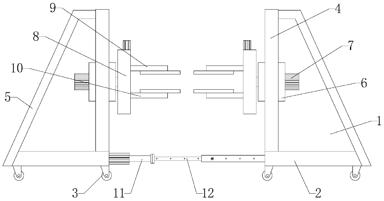
[0025] Such as Figure 1-2 As shown, an overturning mechanism for mattress processing includes two overturning main bodies 1, each overturning main body 1 includes a base 2, universal wheels 3, portal frame 4 and rotating frame 8, universal wheels are installed at the bottom of the base 2 3. A gantry 4 is vertically welded on the top of one side of the base 2. A movable block 6 is arranged inside the gantry 4. A rotating shaft 13 is installed on the movable block 6 through a bearing. One end of the rotating shaft 13 is fixed with a bolt or welded to the rotating The frame 8 is fixedly connected, the other end of the rotating shaft 13 is fixedly connected with the rotary motor 7 through a coupling, a hydraulic cylinder 14 is arranged between the movable block 6 and the top of the base 2, and the hydraulic cylinder 14 is fixed on the base 2 by bolts. The output shaft is fixed on the movable block 6 bottom by bolting or welding.

[0026] Such as Figure 1-2 As shown, a support ...

Embodiment 2

[0029] Such as figure 1 As shown, an electric push rod 11 and a telescopic rod 12 are fixedly connected between the two overturning bodies 1. The electric push rod 11 is horizontally fixed on the side of the base 2 of one of the overturning main bodies 1 through bolts, and the end of the electric push rod 11 is connected to the The end of the telescopic rod 12 is fixedly connected, the telescopic rod 12 is provided with several threaded holes, the telescopic rod 12 is provided with locking bolts for adjusting the length of the telescopic rod 12, and the end of the telescopic rod 12 away from the electric push rod 11 is fixed or welded by bolts It is fixed on the side of the base 2 of the other turning body 1 in the same way.

[0030] By adopting the above-mentioned technical scheme, two overturning main bodies 1 are used to overturn the mattress at the same time, which greatly improves the stability of the mattress overturning, and the width between the two overturning main bo...

Embodiment 3

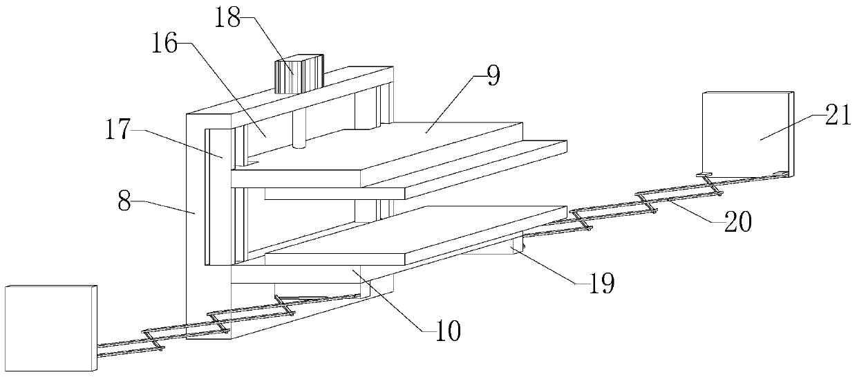
[0032] Such as figure 2 As shown, the left and right ends of the movable block 6 are sleeved on the guide rod 15, and the left and right ends of the movable block 6 are provided with guide holes suitable for the guide rod 15, and the upper and lower ends of the guide rod 15 are respectively fixed on the top of the portal frame 4. and base 2 top.

[0033] By adopting the above technical solution, the up and down movement of the movable block 6 is guided by the guide rod 15, which is beneficial to increase the stability of the movable block 6 driving the rotating frame 8 to move up and down.


PUM


Abstract

The invention discloses an overturning mechanism for mattress processing. The overturning mechanism comprises two overturning bodies. Each overturning body comprises a base, universal wheels, a door frame and a rotating frame. A movable block is arranged inside the door frame. A rotating shaft is mounted on the movable block through a bearing. One end of the rotating shaft is fixedly connected with the rotating frame in a bolt fixing or welding manner, and the other end of the rotating shaft is fixedly connected with a rotating motor through a coupling. A hydraulic cylinder is arranged betweenthe movable block and the top of the base. According to the overturning mechanism for mattress processing, during the overturning process of a mattress, the mattress does not need to be raised to a height in which the mattress can be turned over and then clamped on the rotating frame, and the manpower is saved; and in the process of clamping the mattress, an upper clamping plate, a lower clampingplate and buckle plates cooperate with one another, so that the vertical and horizontal sides of the mattress are simultaneously clamped, the stability of the mattress clamping is improved greatly, and the situation that the mattress slips during the overturning process is avoided.

Description

technical field [0001] The invention relates to the technical field of mattress processing, in particular to a turning mechanism for mattress processing. Background technique [0002] Mattress is an item between the human body and the bed to ensure consumers get a healthy and comfortable sleep. Mattresses are made of various materials, and mattresses made of different materials can bring different sleep effects to people. With the continuous progress of material civilization and technology, the types of mattresses used by modern people are gradually becoming diversified, mainly including: spring mattresses, palm mattresses, latex mattresses, water mattresses, air mattresses, magnetic mattresses, etc. , Among these mattresses, spring mattresses account for a large proportion. During the production and processing process of the mattress, it needs to be turned over by a turning mechanism, so that it is convenient for the staff to carry out related inspections on the mattress. ...

Claims


Application Information

Patent Timeline
Patent Type & Authority Applications(China)
IPC IPC(8): B25H1/10B25H1/16B25B11/00
CPCB25H1/10B25H1/16B25B11/00
Inventor 张玲玲
Owner ANHUI YINGSHANG COUNTY TIANCHENG PRINTING PACKAGING CO LTD
Why Eureka
Try Eureka