A clamp for a plate-shaped device

A device clip, plate-shaped technology, applied in the direction of measuring device, workpiece clamping device, manufacturing tool, etc., can solve the problems affecting the application and test accuracy, such as the influence of the rotation angle movement range of the notebook computer shaft, to achieve good versatility and ensure universality and flexibility, easy loading and unloading effect

Active Publication Date: 2020-11-20
SHANGHAI UNIV
View PDF10 Cites 0 Cited by
  • Summary
  • Abstract
  • Description
  • Claims
  • Application Information

AI Technical Summary

Problems solved by technology

For example, in the scheme of patent ZL201010103922.7, a workbench on which the capacitive touch screen to be tested can be placed on the top surface can be used to place a flat touch screen or a tablet computer; in the scheme of patent ZL201210295129. To measure the ultra-thin carrier structure of the workpiece, place the laptop computer to be tested on it and fix it with clamping blocks in actual use. The disadvantage of this clamping method is that the vibration and structural thickness of the ultra-thin carrier will affect the test accuracy. It has a great influence on the movement range of the notebook computer's shaft angle; in the patent ZL201410224644.9 scheme, a modular and flexible fixture for clamping and fixing computer products is provided, which is composed of several fixture units, each fixture The units can clamp the side structure of the notebook computer, and the units can be horizontally installed on the reference table at any relative position to adapt to the clamping of computer products of different sizes, thereby realizing the mechanical performance of the notebook computer shaft. For automated testing, the solution of flexible fixtures in this method effectively overcomes the shortcomings of the aforementioned method of clamping and fixing the ultra-thin stage, but the operation of fixing and installing the notebook computer to be tested at a time is relatively cumbersome, and each fixture unit needs to be carried out correspondingly one by one. Slack operation, which affects its application in more automated testing situations

Method used


Image

  • A clamp for a plate-shaped device
  • A clamp for a plate-shaped device
  • A clamp for a plate-shaped device

Examples


Embodiment Construction

[0039] Preferred embodiments of the present invention are described in detail below in conjunction with the accompanying drawings, but the following embodiments are only illustrative, and the protection scope of the present invention is not limited by these embodiments.

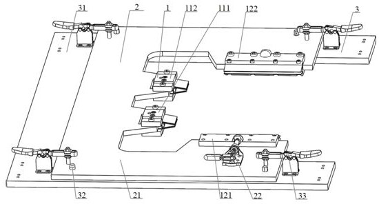
[0040] Such as figure 1 As shown, a plate-shaped device fixture mainly includes a flexible clip module 1, a mounting frame module 2, and a main substrate module 3; wherein the flexible clip module 1 includes a first bottom flexible card with the same structure and internal connection. The clip module 111 and the second bottom flexible clip module 112, as well as the first side flexible clip module 121 and the second side flexible clip module 122, which are identical in structure and internal connection, mainly serve as a clamping plate-shaped device The role; the first bottom flexible card clip module 111 and the second bottom flexible card clip module 112 are fixedly installed on the inner edge of the bottom...


PUM


Abstract

The invention relates to a plate-shaped device clamp, more specifically, the invention relates to a clamp for structure tests oriented to devices, such as notebook computer and flat computer products.The clamp is composed of a flexible clamping module, a mounting rack module and a main base plate module; the flexible clamping module is mainly used for clamping and fixing a plate-shaped device; the mounting rack module is fixedly mounted on the main base plate module, has capability of being quickly separated from the main base plate module and is mainly used for fixedly connecting the flexible clamping module; the main base plate module is used for realizing a clamping and fixing effect on the mounting rack module, and has capability of being connected with a conventional workbench and astandard mechanical frame. The plate-shaped device clamp has the characteristics of having good universality, flexibility, simplicity and convenience in operation and clamping stability, being capableof greatly improving efficiency of automatic test, and so on, moreover, main parts of the clamp are all modularized design, which is convenient for manufacturing and maintenance and also provides possibility for upgrading and rebuilding of the parts, thus, the clamp can be widely used for clamping and fixing the plate-shaped devices.

Description

technical field [0001] The invention relates to a clamp suitable for clamping a plate-shaped device. More specifically, the present invention relates to a fixture required for structural testing of devices such as notebook computers and tablet computer products. Background technique [0002] For automated testing of important components such as shafts and touch screens in laptops, tablet computers, etc., it is first necessary to effectively fix the device to be tested, and usually select a regular board-shaped structure in the device for fixing operations, such as the keyboard board of a laptop. to fix. [0003] A conventional fixing method is to provide a tray structure for placing and fixing the plate-shaped structural components in the device to be tested. For example, in the scheme of patent ZL201010103922.7, a workbench on which the capacitive touch screen to be tested can be placed on the top surface can be used to place a flat touch screen or a tablet computer; in t...

Claims


Application Information

Patent Timeline
Patent Type & Authority Patents(China)
IPC IPC(8): G01M13/00B25B11/00
CPCB25B11/00G01M13/00
Inventor 贾文川张晓龙孙翊蒲华燕马书根
Owner SHANGHAI UNIV
Why Eureka
Try Eureka