Valve coupling vibration testing device and testing method

A testing device, a technology of coupling vibration, applied in vibration testing, measuring devices, mechanical valve testing, etc., can solve problems such as waste, and achieve the effect of saving experimental costs

Active Publication Date: 2019-08-20
ZHEJIANG UNIV
View PDF8 Cites 7 Cited by
  • Summary
  • Abstract
  • Description
  • Claims
  • Application Information

AI Technical Summary

Problems solved by technology

Purchasing different types of actuators just to perfo

Method used


Image

  • Valve coupling vibration testing device and testing method
  • Valve coupling vibration testing device and testing method
  • Valve coupling vibration testing device and testing method

Examples


Embodiment Construction

[0036] The present invention will be further described below in conjunction with the accompanying drawings and specific embodiments.

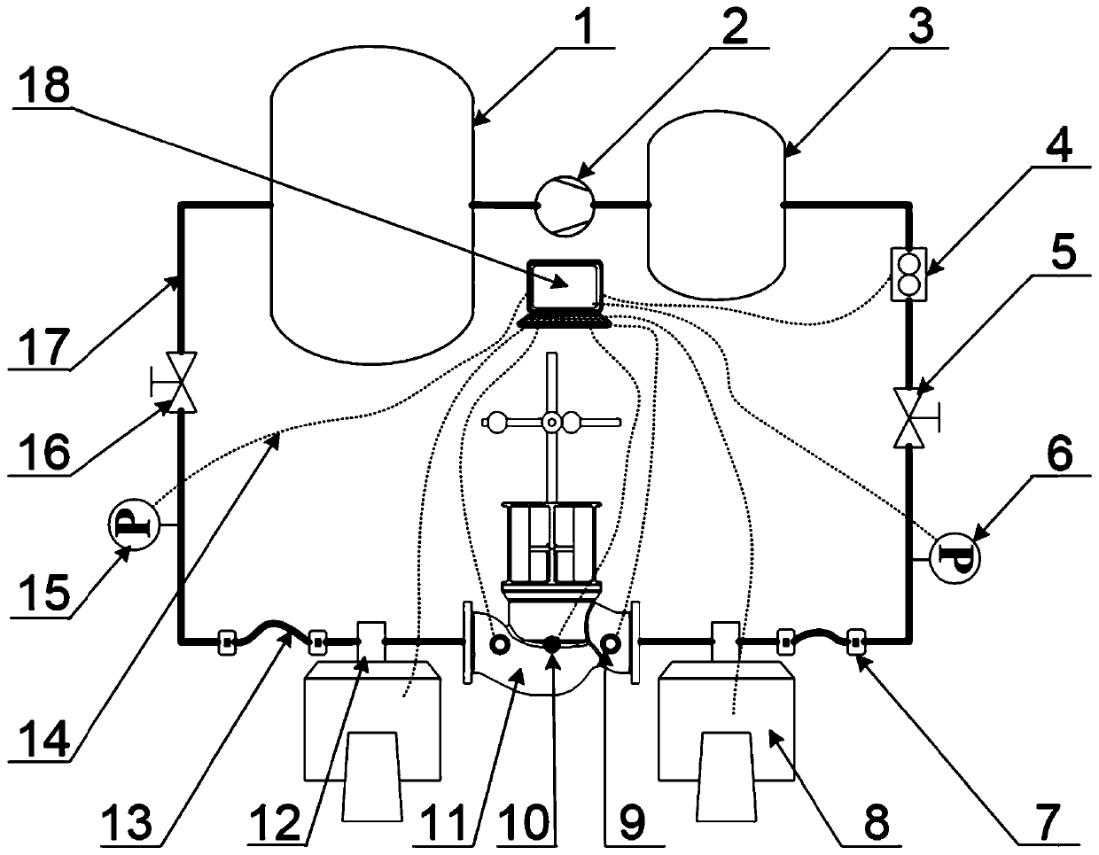
[0037] Such as figure 1 Shown, in the valve coupling vibration testing device of the present invention, by storage tank 1, power machinery 2, surge tank 3, flow meter 4, upstream control valve 5, upstream pressure gauge 6, valve to be tested 11, downstream pressure gauge 15 and The downstream control valve 16 is sequentially connected with the pressure-resistant hose 13 through the metal pipeline 17 to form a fluid flow circuit. The storage tank 1 is used to store fluid, and the buffer tank 3 is used to stabilize the pressure. The power machine 2 includes a water pump and a compressor for providing power for fluid flow. For the valve with liquid as the working medium, the power machine 2 is a water pump; for the valve with gas as the working medium, the power machine 2 is a compressor. The flowmeter 4 is used to measure the flow rate in the ...


PUM


Abstract

The invention discloses a valve coupling vibration testing device and a testing method. The test device comprises a storage tank, power machinery, a buffer tank, a flow meter, an upstream control valve, an upstream pressure gauge, a valve to be tested, a downstream pressure gauge and a downstream control valve which are sequentially connected to a pressure withstanding flexible pipe through a metal pipeline to form a fluid flow loop. External excited vibration excitation is provided by a vibration bench. A vibration acceleration sensor and a strain gauge are arranged on the valve to be testedand are used for measuring vibration acceleration and dynamic strain respectively, and a center of gravity adjustment mechanism is installed to replace an execution mechanism. In the invention, external excited vibration of valves, flow-excited vibration and coupling vibration when the two work together of different working media, different structural forms and different working conditions can beinvestigated, and the vibration caused by collision of components is distinguished through testing the valves of different assembling forms.

Description

technical field [0001] The invention relates to a valve vibration test, in particular to a vibration test system for investigating externally induced vibration and flow-induced vibration of a valve, overall vibration and coupling vibration caused by parts collision. Background technique [0002] The valve realizes the control of process parameters such as fluid pipeline pressure and flow rate by changing the size of the flow area. Valves are one of the sources of vibration in fluid lines due to their strong throttling action. The vibration of the valve will cause harm to equipment and operators. At present, with the continuous emergence of various harsh working conditions, the problem of valve vibration has become more and more prominent. Therefore, it is of practical and important significance to investigate and study the valve vibration problem. [0003] Valve vibration can be divided into externally induced vibration and flow-induced vibration according to the source. ...

Claims


Application Information

Patent Timeline
IPC IPC(8): G01M13/003G01M7/02
CPCG01M7/022G01M13/003
Inventor 钱锦远吴嘉懿侯聪伟金志江
Owner ZHEJIANG UNIV
Why Eureka
Try Eureka