Battery cell fusing bar

A cell and fusing technology, applied in the direction of batteries, circuits, electrical components, etc., can solve the problems of short circuit of cells, increasing the complexity of battery structure, and endangering personal safety.

Pending Publication Date: 2019-08-20
JIANGXI GANFENG BATTERY TECH
View PDF6 Cites 0 Cited by
  • Summary
  • Abstract
  • Description
  • Claims
  • Application Information

AI Technical Summary

Problems solved by technology

Because batteries are usually used at high risk or short-circuited during use, resulting in fire and combustion accidents, which are more likely to endanger personal safety
At present, the way to solve this problem is generally to connect some safety protection components outside the battery case to achieve the protection effect. For example, Chinese patent CN201610176088 and patent CN101567432 both achieve this purpose by adding some protective structural parts on the upper end of the battery case. The use of batteries has caused many restrictions, and the external components have increased the complexity of the battery structure and increased the cost of using the battery

Method used


Image

  • Battery cell fusing bar
  • Battery cell fusing bar
  • Battery cell fusing bar

Examples


Embodiment 1

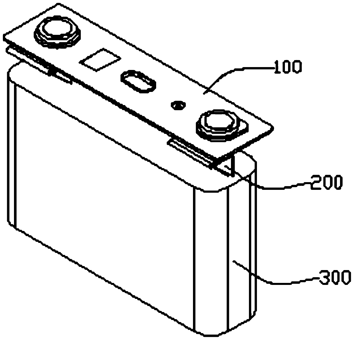
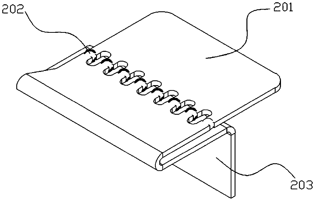
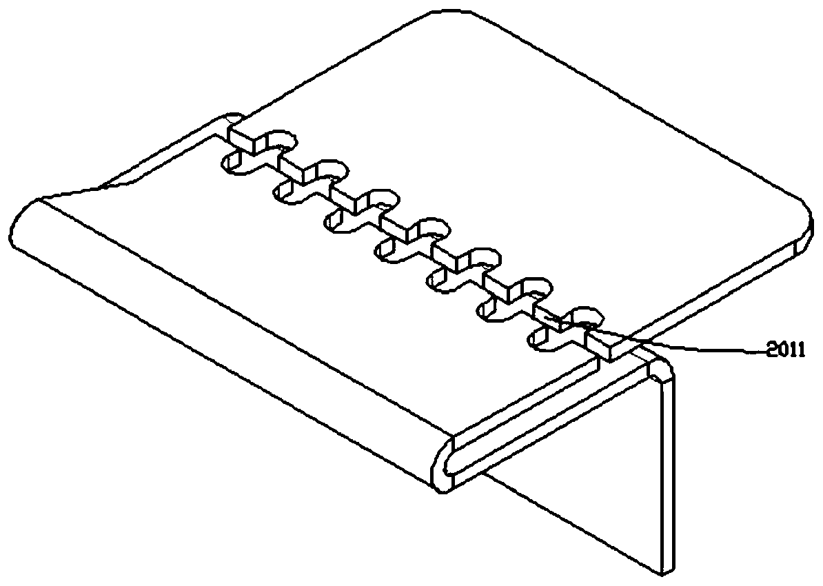
[0023] see Figure 1-Figure 3 , a cell fuse bar provided by the present invention includes a connecting bar 200, the connecting bar 200 has a connecting groove 2011, and the connecting groove divides the connecting bar into two parts, called the first part 201 and the second part. Part 203, the first part 201 is used to connect the cell top cover 100, one end of the second part 203 is used to connect the cell body 300, and the connecting groove 2011 includes a set of arc-shaped grooves, which are used to closely contact and connect a set of melting beads 202 , the shape of the melting bead matches the arc groove, the melting bead 202 and the connection bar 200 are both conductors, and the melting point of the melting bead 202 is lower than the melting point of the connecting bar 200 .

[0024] In the electric core fusing bar provided by the present invention, when the current is overloaded or short-circuited, when the current flows through the melting bead, the melting point o...

Embodiment 2

[0026] On the basis of the embodiment, the first part is connected to the cell top cover by laminated polymer diffusion welding to form a soft connection, and one end of the second part is connected to the cell body by laminated polymer diffusion welding to form a soft connection . Polymer diffusion welding can ensure the stability of the connection row size and material.

Embodiment 3

[0028] On the basis of embodiment 2, the material of the connecting bar may be copper or aluminum, and the material of the melting bead is a material with high conductivity, specifically one of silver, copper, aluminum and the like. For example, when the material of the connecting row is copper, the material of the melting bead is aluminum or silver; when the material of the connecting row is aluminum, the material of the melting bead is silver.


PUM

PropertyMeasurementUnit
Thicknessaaaaaaaaaa

Abstract

The invention relates to the technical field of batteries and discloses a battery cell fusing bar. The battery cell fusing bar comprises a connection bar having a connection groove, the connection groove breaks the connection bar into two parts, one part is used to connect with a battery cell top cover, one end of the second part is connected with a battery cell body, the connection groove comprises a set of arc grooves configured to in tight contact with and connect with a set of molten beads, the molten beads are matched with the arc-shaped grooves in shape, the molten beads and the connection bar are conductors, and the melting points of the molten beads are lower than the melting point of the connection bar. According to the battery cell fusing bar, when the current is overloaded or short-circuited, and the current flows through the molten beads, the molten state occurs because the melting point of the molten beads is lower than that of the connection bar; and when the current is continuously overloaded, the molten beads are further reduced, so that a gap is formed between the molten beads and the connection groove, and the first part and the second part of the connection bar are disconnected, thereby playing a role in power-off protection.

Description

technical field [0001] The invention relates to the technical field of new energy power batteries, in particular to a battery cell fuse bar. Background technique [0002] At present, with the increasing miniaturization, portability and portability of electronic products, such as cameras, notebooks and mobile phones, the driving power of these electronic products is also developing in the direction of high capacity, high safety and portability. Its excellent characteristics such as high capacity are widely used in electronic products. [0003] The lithium battery includes a shell, a cover plate, and a battery cell, etc., wherein the battery core is placed inside the shell, the upper end of the shell has an upper end opening, and the cover plate is closed on the upper end opening of the shell, and then formed on the cover plate If the electrode terminals are connected, the lithium battery can be electrically connected with external electronic components to realize power suppl...

Claims


Application Information

Patent Timeline
IPC IPC(8): H01M2/34
CPCH01M2200/00H01M50/572Y02E60/10
Inventor 黄夏亮沈海博程宝利程军华熊刚庭孔卫忠尹世飞熊亚昆
Owner JIANGXI GANFENG BATTERY TECH
Why Eureka
Try Eureka