Suspension pneumatic lifting device and suspension pneumatic lifting method

A lifting device and hoisting technology, which is applied in the direction of transportation and packaging, load hanging components, etc., can solve the problem that the pneumatic balancer cannot realize the full suspension lifting of heavy objects of different weights, reduce the availability of production capacity, and reduce the suspension lifting capacity of the pneumatic balancer. Heavy range and other issues to achieve the effect of improving assembly accuracy and production efficiency, reducing response time, and high positioning accuracy

Pending Publication Date: 2017-02-22
SOUTH CHINA UNIV OF TECH +1
View PDF0 Cites 0 Cited by
  • Summary
  • Abstract
  • Description
  • Claims
  • Application Information

AI Technical Summary

Problems solved by technology

However, for non-production line assembly occasions, this type of pneumatic balancer cannot realize the full-range suspension and lifting of heavy objects of different weights, and the operator needs to prov

Method used


Image

  • Suspension pneumatic lifting device and suspension pneumatic lifting method
  • Suspension pneumatic lifting device and suspension pneumatic lifting method

Examples


Embodiment 1

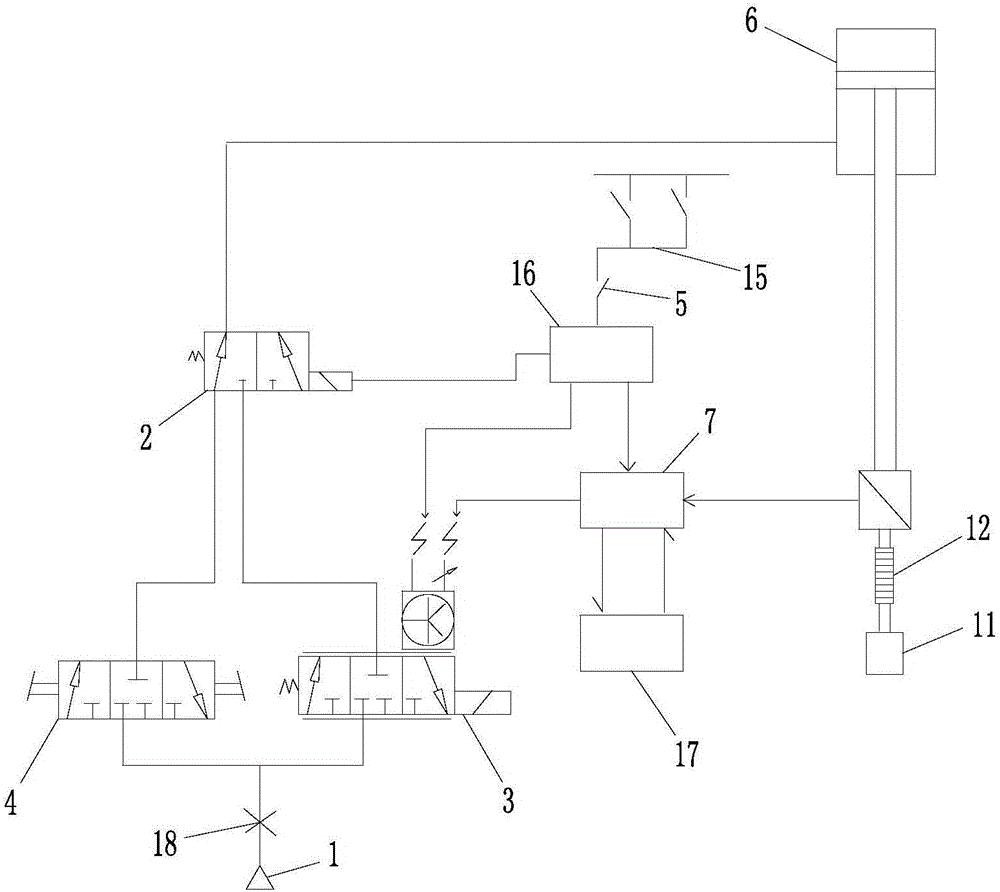
[0049] A suspended pneumatic lifting device, including an air source 1, a power supply connection circuit, a reversing valve 2, an electrical proportional valve 3, a two-position three-way solenoid valve 4, a normally-off switch 5, a pneumatic lifting device 6, a controller 7, a single The directional valve 18 and the tension sensor, the directional valve and the electric proportional valve are respectively connected with the air source and the two-position three-way solenoid valve, the two-position three-way solenoid valve is connected with the pneumatic lifting device, and the power access circuit has a function for controlling the electric proportional Valve, two-position three-way solenoid valve and normally-off switch for power supply of the controller, and the one-way valve is set on the output port of the air source;

[0050] The tension sensor is set on the execution end of the pneumatic lifting device to measure the weight of the lifting object;

[0051] The tension s...

Embodiment 2

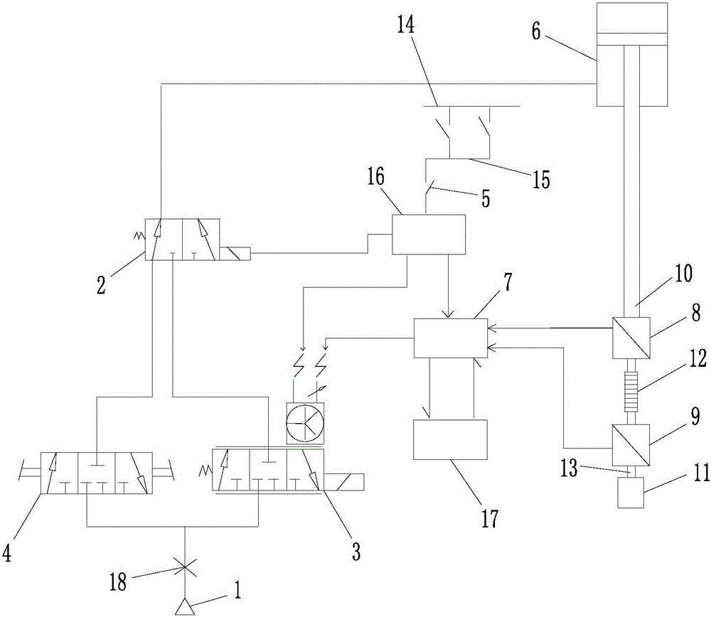
[0057] The difference between this embodiment and Embodiment 1 is that the tension sensor includes a first tension sensor 8 and a second tension sensor 9, the first tension sensor is connected to the execution end 10 of the pneumatic lifting device, and the second tension sensor is connected to the second tension sensor. a tension sensor below;

[0058] The first tension sensor and the second tension sensor are respectively connected to the controller, and the first tension sensor is used to measure the total weight of the object connected thereunder;

[0059] The second tension sensor is used to measure the weight of the hoisting object 11;

[0060] The controller is used to receive the detection data of the first tension sensor and the second tension sensor, and compare the two detection data values, if the difference between the two detection data values ​​is less than the set value, control the electric proportional valve The one-position three-way solenoid valve is conne...


PUM


Abstract

The invention discloses a suspension pneumatic lifting device and a suspension pneumatic lifting method. Specifically, the suspension pneumatic lifting device comprises a gas source, a power access circuit, a reversing valve, an electropneumatic proportional valve, a two-position three-way electromagnetic valve, a pneumatic lifting apparatus, a controller and a tension sensor. The reversing valve and the electropneumatic proportional valve are respectively connected to the gas source and the two-position three-way electromagnetic valve, the two-position three-way electromagnetic valve is in connection with the pneumatic lifting apparatus, and the power access circuit has a control switch for controlling power supply to the electropneumatic proportional valve, the two-position three-way electromagnetic valve and the controller. The controller compares the test data value with a set value, if the test data value is smaller than the set value, the electropneumatic proportional valve is controlled for communicating an air inlet with the two-position three-way electromagnetic valve, if the test data value is greater than the set value, the electropneumatic proportional valve is controlled for communicating an air outlet with the two-position three-way electromagnetic valve. The suspension pneumatic lifting device and the suspension pneumatic lifting method provided by the invention can realize rapid raising and descending of a hoisted object with any weight.

Description

technical field [0001] The invention relates to the technical field of lifting equipment, in particular to a suspension pneumatic lifting device and a suspension pneumatic lifting method. Background technique [0002] At present, domestic hoisting equipment mainly includes pneumatic hoist, electric hoist, and pneumatic balance crane. In the mechanical production and assembly industry, especially where high positioning accuracy is required, air hoists and electric hoists generally cannot meet the requirements. At present, the domestic pneumatic control technology is developing very rapidly, and the application of pneumatic balance cranes is becoming more and more extensive. It realizes the suspension function of constant weight materials near the balance point, and provides convenient conditions for my country's assembly industry. However, the pneumatic balance cranes currently on the market use a separate control method for no-load balance and heavy-load balance in terms of...

Claims


Application Information

Patent Timeline
IPC IPC(8): B66C1/00B66C13/14
CPCB66C1/00B66C13/14
Inventor 屈盛官尹嵘李小强胡欣钧
Owner SOUTH CHINA UNIV OF TECH
Why Eureka
Try Eureka