
Novel eddy current retarder rotor

An eddy current retarder and rotor technology, which is applied to electrical components, electromechanical devices, electric components, etc., can solve the problems of complex production and casting of double-layer structures, high manufacturing and maintenance costs, and reduced rotor structural strength. Small deformation, small wind resistance and good heat dissipation efficiency

Pending Publication Date: 2019-08-20
TELMA AUTOMOBILE BRAKING SYST SHANGHAI
View PDF0 Cites 0 Cited by
  • Summary
  • Abstract
  • Description
  • Claims
  • Application Information

AI Technical Summary

Problems solved by technology

[0004] The rotors in the prior art have at least the following defects: (1) The rotor adopts a "double-layer structure", which is too heavy for a small torque retarder, and the production and casting of the double-layer structure of the rotor is relatively complicated, and it is difficult to remove sand, which is not conducive to heat dissipation , not easy to clean
It can be said that the manufacturing and maintenance costs are very high; (2) The rotors in the prior art can only be obtained by ordinary casting methods, and defects such as sand holes are prone to occur inside the rotor, resulting in a reduction in the internal structural strength of the rotor and a reduction in the life of the rotor

Method used


Image

  • Novel eddy current retarder rotor
  • Novel eddy current retarder rotor
  • Novel eddy current retarder rotor

Examples


Embodiment Construction

[0028] Specific embodiments of the present invention will be described in detail below in conjunction with the accompanying drawings. However, the present invention should be understood as not limited to such embodiments described below, and the technical idea of ​​the present invention can be implemented in combination with other known technologies or other technologies having the same functions as those known technologies.

[0029] In the description of the following specific embodiments, in order to clearly demonstrate the structure and working mode of the present invention, many directional words will be used to describe, but "front", "rear", "left", "right", "outer Words such as ", "inwardly", "outwardly", "inwardly", "axially" and "radially" are to be understood as convenient terms and should not be understood as limiting terms.

[0030] In the present invention, unless otherwise clearly specified and limited, terms such as "installation", "connection", "connection" and ...


PUM


Abstract

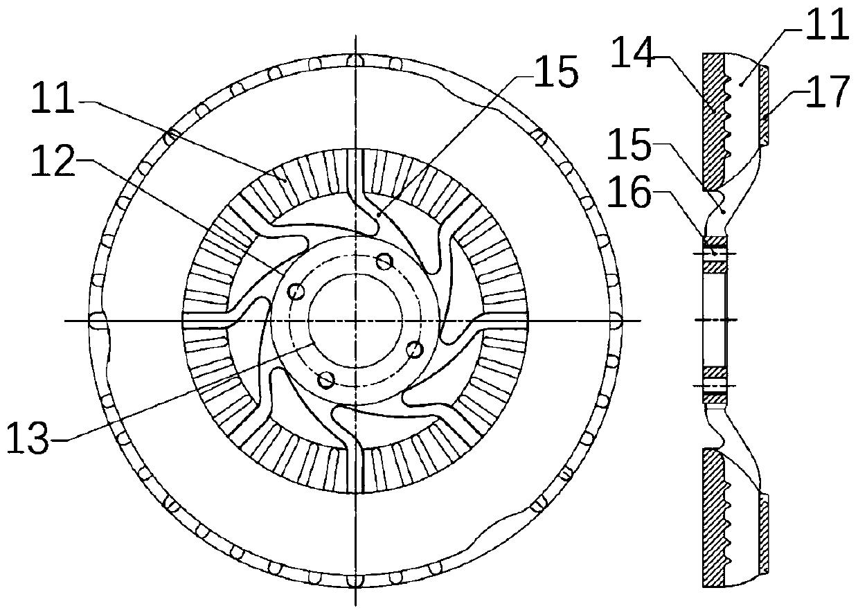
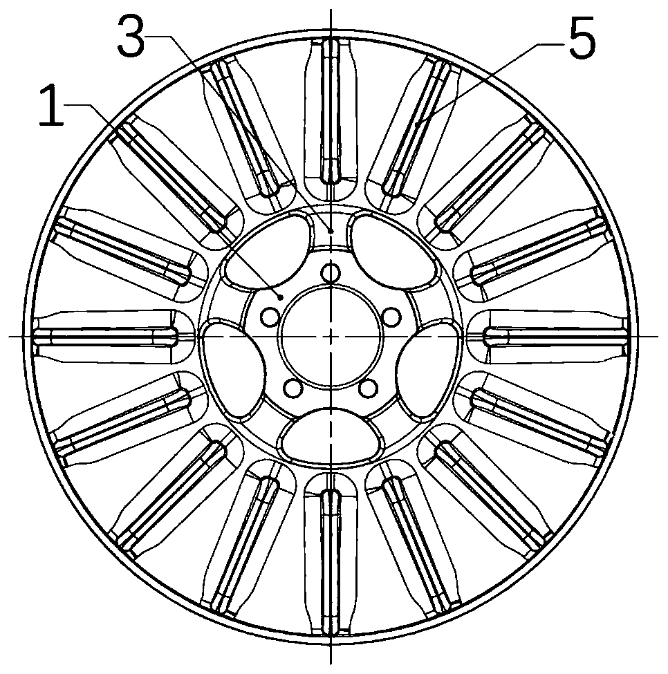
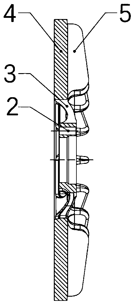
The invention discloses a novel eddy current retarder rotor. The novel eddy current retarder rotor comprises a flange connection structure, connection holes, a connection rib, a large flange surface structure, radiating fins and a flange seam allowance. The flange seam allowance is located at the center of the inner side of the flange connection structure, the connection holes are uniformly arranged around the flange seam allowance, one end of the connection rib is connected with the flange connection structure, the other end thereof is connected with the large flange surface structure, the radiating fins are distributed on the large flange surface structure, and the main body of the eddy current retarder rotor is arranged as a single-layer structure. Compared to the prior art, the structure is concise, the heat dissipation efficiency is high, the wind resistance is small, the durability is good, the production and manufacture are simple, and the maintenance cost is low.

Description

technical field [0001] This patent relates to an eddy current retarder, in particular to a novel eddy current retarder rotor. Background technique [0002] At present, the safety problem of road driving has been paid more and more attention by people from all walks of life. At the same time, Clause 5.8.1 on page 26 of GB12676-2014 clearly requires that M3 passenger cars must meet the requirements of Type IIA test. However, domestic passenger car manufacturers install auxiliary brakes for exhaust brakes, which can no longer meet the requirements of regulatory tests. It can be seen that the new small mid-mounted eddy current retarder is the development trend of this type of vehicle installation. At present, the domestic small mid-mounted eddy current retarder is basically a reduced version of the large mid-mounted eddy current retarder, and the same is true for the rotor. The heat sink between the flange surface structures is difficult to remove sand, and the heat sink struc...

Claims


Application Information

Patent Timeline
IPC IPC(8): H02K9/22
CPCH02K9/22
Inventor 陈华朱俊
Owner TELMA AUTOMOBILE BRAKING SYST SHANGHAI
Learn More