Aviation different-speed image motion compensation circuit, CCD driving circuit and driving method

A technology of image movement compensation and driving circuit, which is applied in the field of aerial image processing to ensure the consistency of timing and improve the effect.

Active Publication Date: 2019-08-20
CHANGCHUN INST OF OPTICS FINE MECHANICS & PHYSICS CHINESE ACAD OF SCI
View PDF11 Cites 2 Cited by
  • Summary
  • Abstract
  • Description
  • Claims
  • Application Information

AI Technical Summary

Problems solved by technology

[0005] The purpose of the present invention is to provide a kind of aviation variable speed image motion compensation circuit, CCD driving circuit and driving method, aiming to solve the technical problem of simple and low-cost realization of aviation variable speed image motion compensation in the prior art

Method used


Image

  • Aviation different-speed image motion compensation circuit, CCD driving circuit and driving method
  • Aviation different-speed image motion compensation circuit, CCD driving circuit and driving method
  • Aviation different-speed image motion compensation circuit, CCD driving circuit and driving method

Examples


Embodiment 1

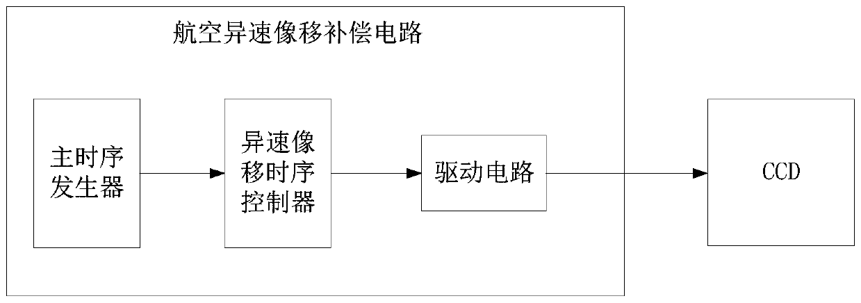
[0031] as attached figure 1 As shown, the aerial variable speed image motion compensation circuit provided in this embodiment includes: a main timing generator, a variable speed image motion timing controller and a driving circuit.

[0032] The main timing generator is used to generate the driving timing required by the CCD; the different speed image motion timing controller is used to forward the driving timing generated by the main timing generator, and to generate the image motion compensation driving timing during the different speed image motion compensation; The driving circuit is used for amplifying and shifting the driving timing output by the different-speed image shift timing controller to drive the CCD.

[0033] By adding a main timing generator to the aviation variable-speed image motion compensation circuit, the main timing generator uniformly calculates various compensation parameters during variable-speed image motion compensation, effectively ensuring the timin...

Embodiment 2

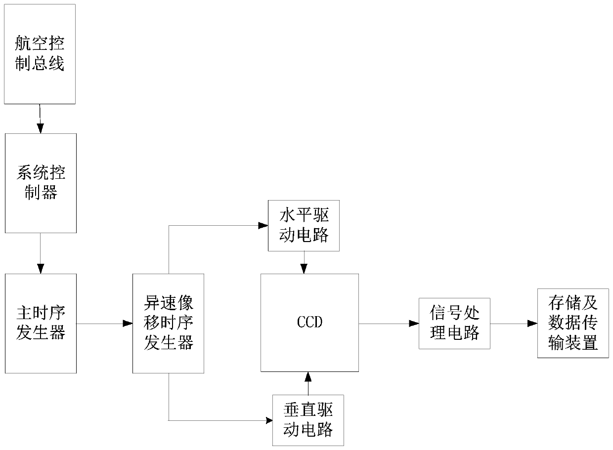
[0039] as attached figure 2 As shown, the CCD driving circuit provided by this embodiment includes: the above-mentioned aviation control bus, a system controller, an aviation variable speed image motion compensation circuit and a signal processing circuit.

[0040] The aviation control bus, the system controller, the aviation variable speed image motion compensation circuit and the signal processing circuit are sequentially connected by communication.

[0041] Among them, the aviation variable speed image motion compensation circuit includes a main timing generator, a variable speed image motion timing controller and a driving circuit.

[0042] The causes of variable speed image motion, the principle of variable speed image motion compensation and the CCD driving circuit provided by this embodiment will be described below.

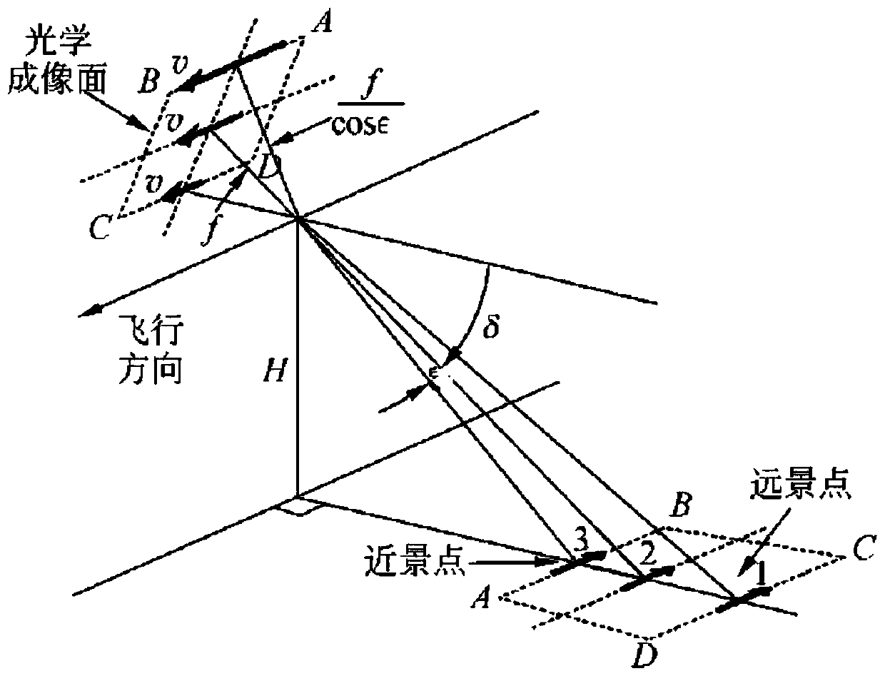
[0043] 1. Analysis of different velocity image motion

[0044] When the area array CCD camera is tilted to take pictures, because the plane is tilted, ...

Embodiment 3

[0076] Embodiment 3 shows a kind of CCD drive method, it is characterized in that, comprises:

[0077] Calculate the forward image movement speed according to the given lens focal length fl, depression angle δ, field of view θ and aircraft speed-to-height ratio V / H;

[0078] The column pixels of the CCD are divided into several blocks according to the forward image movement speed, and each block corresponds to a corresponding charge moving rate;

[0079] The main timing generator in the aviation variable speed image motion compensation circuit generates horizontal transfer timing according to the charge moving rate, generates vertical transfer timing when no image motion occurs, and generates vertical transfer timing required for variable speed image motion, and through different The speed image shift timing controller controls the drive circuit to drive the CCD;

[0080] The CCD receives the signal of the image motion compensation circuit, and changes the charge transfer spe...


PUM


Abstract

The invention is applicable to the technical field of displays, and provides an aviation different-speed image motion compensation circuit, which comprises a main time sequence generator, used for generate driving time sequence required by a CCD; a different-speed image motion time sequence controller, used for forwarding the driving time sequence generated by the main time sequence generator andgenerating an image motion compensation driving time sequence during different-speed image motion compensation; and a driving circuit used for amplifying and translating the driving time sequence output by the different-speed image motion time sequence controller so as to drive the CCD. The main time sequence generator is added to the aviation different-speed image motion compensation circuit, andthe main time sequence generator uniformly calculates various compensation parameters during different-speed image motion compensation, so that the time sequence consistency during different-speed image motion compensation is effectively ensured, and the effect of different-speed image motion compensation is better improved.

Description

technical field [0001] The invention belongs to the technical field of aerial image processing, and in particular relates to an aerial image motion compensation circuit at different speeds, a CCD driving circuit and a driving method. Background technique [0002] In the reconnaissance process, the reconnaissance plane often needs to fly at high speed and low altitude (high speed and height ratio) in order to avoid radar surveillance. At this time, image motion blur will inevitably appear in aerial imaging. The formation of image motion blur is closely related to the flight attitude of the carrier aircraft. Different parameters such as the flight speed, altitude, roll angle, yaw angle, and pitch angle of the carrier aircraft will produce different image motion forms. Among them, when the carrier aircraft is flying sideways or the lens is pitched to the side, the aerial camera on the carrier aircraft will be in a squint working state. At this time, different positions on the ...

Claims


Application Information

Patent Timeline
Patent Type & Authority Applications(China)
IPC IPC(8): H04N5/372H04N5/378
CPCH04N25/71H04N25/75
Inventor 任航胡涛涛宋玉龙
Owner CHANGCHUN INST OF OPTICS FINE MECHANICS & PHYSICS CHINESE ACAD OF SCI
Why Eureka
Try Eureka