Circulating water mattress
A technology for circulating water and mattresses, applied in mattresses, spring mattresses, beds, etc., can solve the problem of noise affecting sleep quality, etc., and achieve the effect of low noise and strong adaptability
- Summary
- Abstract
- Description
- Claims
- Application Information
AI Technical Summary
Problems solved by technology
Method used
Image
Examples
Embodiment 1
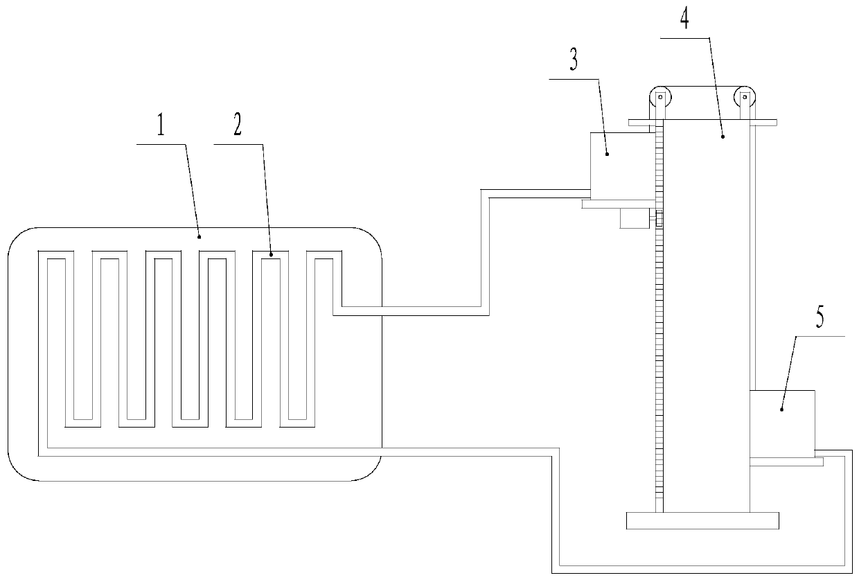
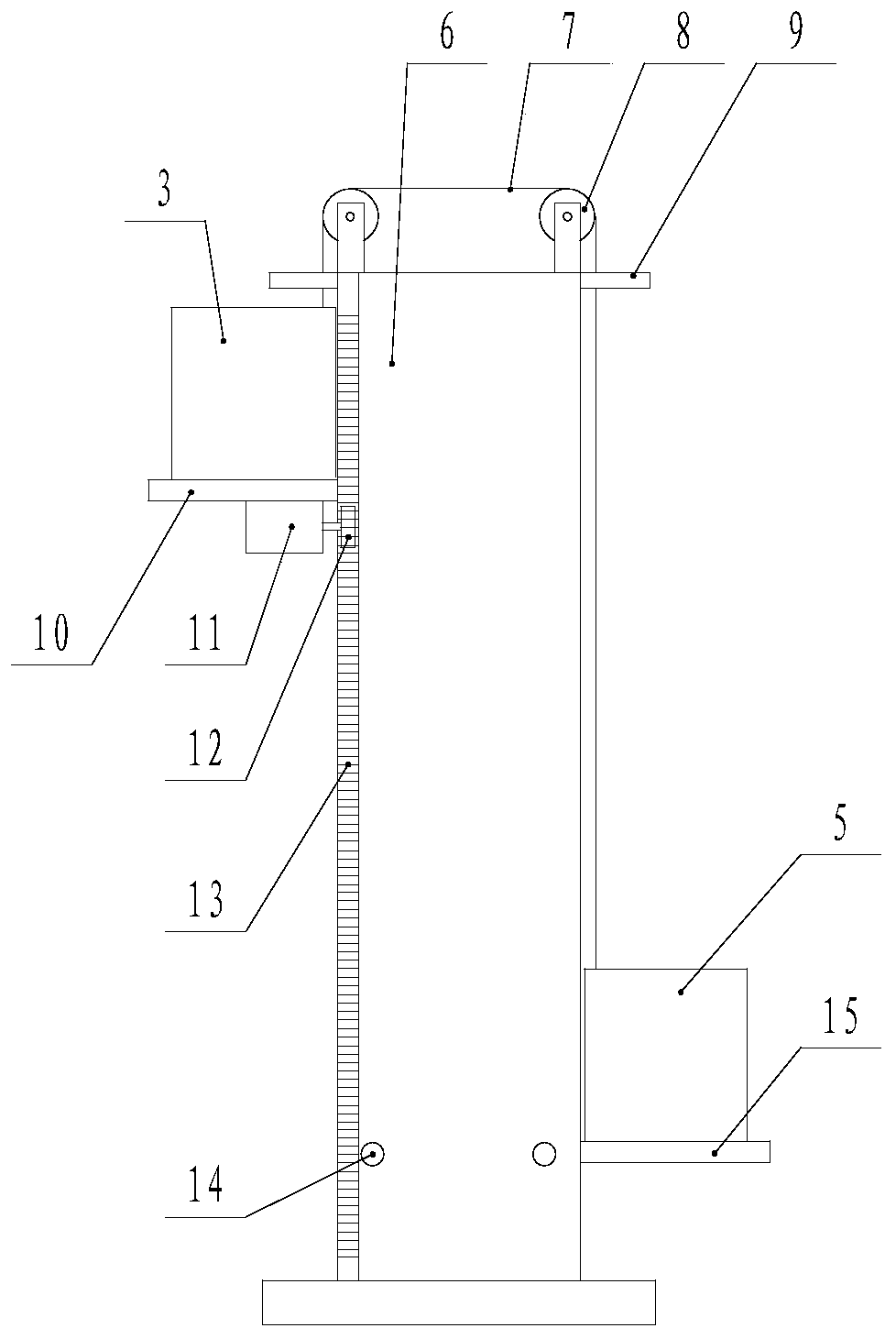
[0023] Such as figure 1 , figure 2 As shown, the circulating water mattress described in this embodiment includes a mattress 1, a bent water pipe 2 is arranged in the mattress 1, a first water tank 3, a second water tank 5 and a lifting device 4, and the bent water pipe 2 The two ends of the interface are respectively connected with the first water tank 3 and the second water tank 5, the lifting device 4 includes a frame body 6, a lifting transmission device, a first lifting frame 10 and a second lifting frame 15, the first water tank 3 and the second water tank 5 They are respectively fixed on the first lifting frame 10 and the second lifting frame 15, and the lifting transmission device is respectively connected with the first lifting frame 10 and the second lifting frame 15 in transmission.
[0024] During work, in this embodiment, the first water tank 3 and the second water tank 5 maintain a certain height difference through the lifting device 4, and add cold water or ho...
Embodiment 2
[0026] Such as figure 2 , image 3 As shown, the lifting transmission device of the present embodiment includes a traction rope 7, a pulley 8, a motor 11, a gear 12 and a rack 13, the traction rope 7 bypasses the pulley 8, and the two ends are fixedly connected to the first lifting frame 10 and the second lifting frame respectively. On the two lifting frames 15, the motor 11 is fixed on the first lifting frame 10 or the second lifting frame 15, the gear 12 is connected with the output shaft of the motor 11, the rack 13 is fixed on the frame body 6, and the gear 12 and the rack 13 are engaged. The lifting transmission device is used to automatically realize the conversion of the height positions of the first water tank 3 and the second water tank 5 .
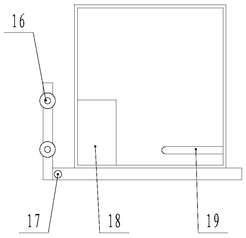
[0027] Preferably, the first lifting frame 10 and the second lifting frame 15 are movably connected with the frame body 6 through the chute on the frame body 6 respectively, the first lifting frame 10 and the second lifting fra...
Embodiment 3
[0032] Such as figure 2 , image 3 As shown, in this embodiment, two pin holes A14 are provided at the bottom of the frame body 6 , and a pin hole B17 corresponding to the pin hole A14 is respectively provided on the first lifting frame 10 and the second lifting frame 15 .
[0033] This embodiment is mainly used when there is a power failure or no power supply. When the pin hole A14 of the first lifting frame 10 and the second lifting frame 15 is lowered to align with the pin hole B17, a pin shaft is inserted between the pin hole A14 and the pin hole B17. , realizing the fixing of the height of the first lifting frame 10 and the second lifting frame 15.
[0034] Other contents of this embodiment are the same as those of Embodiment 1.
PUM
 Abstract
Description
Claims
Application Information
 - R&D
- Intellectual Property
- Life Sciences
- Materials
- Tech Scout
- Unparalleled Data Quality
- Higher Quality Content
- 60% Fewer Hallucinations
Browse by: Latest US Patents, China's latest patents, Technical Efficacy Thesaurus, Application Domain, Technology Topic, Popular Technical Reports.
© 2025 PatSnap. All rights reserved.Legal|Privacy policy|Modern Slavery Act Transparency Statement|Sitemap|About US| Contact US: help@patsnap.com


