
Carburization equipment and carburization method

A carburizing and equipment technology, applied in metal material coating process, coating, solid-state diffusion coating, etc., can solve the problems of oxidation and affecting the heating equipment of the carburizing chamber, so as to simplify the loading procedure and protect the heating equipment. Effect

Pending Publication Date: 2019-08-23
江苏丰东热技术有限公司
View PDF0 Cites 3 Cited by
  • Summary
  • Abstract
  • Description
  • Claims
  • Application Information

AI Technical Summary

Problems solved by technology

In this case, if the processed product is carried in and out, the carburizing chamber will be oxidized due to the oxidizing components in the atmosphere, which will affect the heating material in the carburizing chamber.

Method used


Image

  • Carburization equipment and carburization method
  • Carburization equipment and carburization method
  • Carburization equipment and carburization method

Examples


no. 1 example

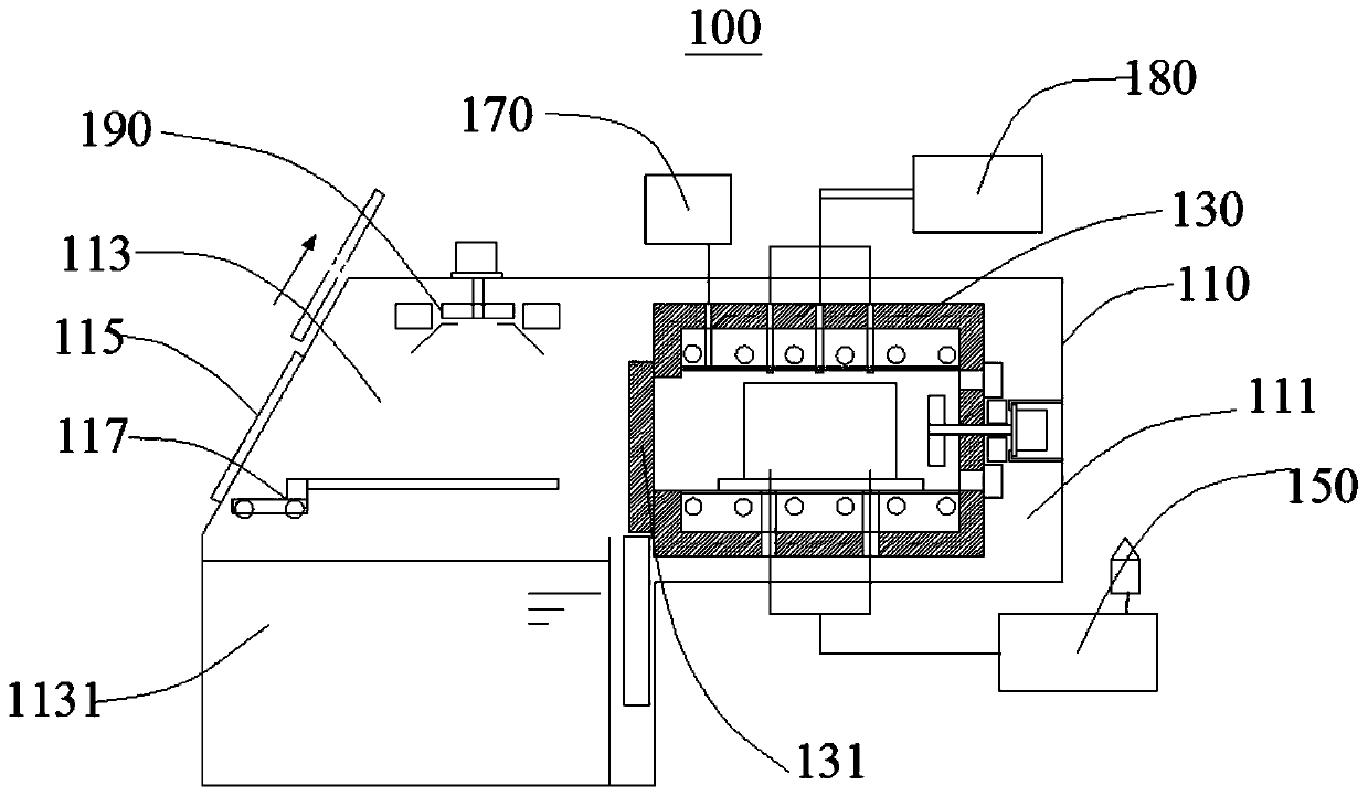
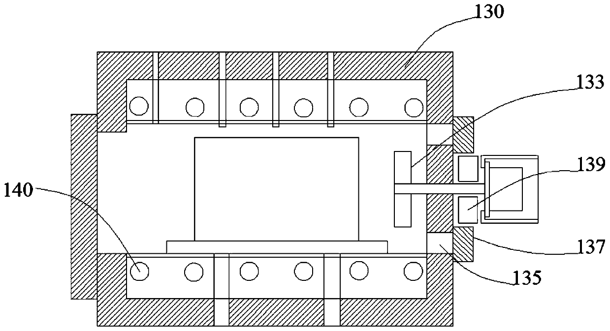
[0040] see figure 1, the present embodiment provides a carburizing equipment 100, including a housing housing 110, a heating chamber 130, a vacuum processing device 150, an exhaust gas inlet device 170 and a carburizing gas inlet device 180, the housing housing 110 There is a carburizing zone 111 and a cooling zone 113 which communicate with each other. The heating chamber 130 is arranged in the carburizing zone 111. A heat-sealed door 131 is opened at one end of the heating chamber 130 to isolate the inside of the heating chamber 130 from the cooling zone 113. The air inlet device 170 is connected to the heating chamber 130, and is used to feed exhaust gas into the heating chamber 130, and the carburizing gas inlet device 180 is connected to the heating chamber 130, and is used to feed carburizing gas into the heating chamber 130. , the bottom of the heating chamber 130 is provided with a flow hole communicating with the carburizing area 111 , and the vacuum treatment device ...

no. 2 example

[0067] see Figure 5 , this embodiment provides a carburizing method, which is suitable for the carburizing equipment 100 provided in the first embodiment.

[0068] The carburizing method provided by the present embodiment comprises the following steps:

[0069] S1: Load the workpiece into the cooling zone 113.

[0070] Specifically, open the feeding door 115 on the accommodating housing 110 , use the feeding device 117 to send the workpiece into the feeding port, and stay in the cooling zone 113 .

[0071] S2: Pass exhaust gas into the heating chamber 130 .

[0072] Specifically, nitrogen gas is fed into the heating chamber 130 through the exhaust gas inlet device 170, so that the heating chamber 130 is filled with nitrogen gas, and air entering the cooling zone 113 from the feeding port is prevented from entering the heating chamber 130 through the flow holes. During actual charging, because the inside of the heating chamber 130 is high temperature, the heat-sealed door 1...


PUM


Abstract

The invention provides carburization equipment and a carburization method, and relates to the technical field of carburization. The carburization equipment comprises a containing shell, a heating chamber, a vacuum processing device, an exhausted gas injection device and a carburization gas injection device; before vacuumizing, exhausted gas can be injected into the heating chamber through the exhausted gas injection device, and the situation that when a workpiece is loaded into a cooling zone from the outside, air enters the heating chamber, and a heating device is influenced is avoided. Meanwhile, the vacuum processing device is connected with the containing shell and the heating chamber, thus, the containing shell can be subjected to integral vacuumizing, the heating chamber communicateswith the carburization zone, the heating chamber can be in the vacuum state during vacuumizing, accordingly, a heat sealing door can be opened in the vacuum state, and the workpiece is loaded into the heating chamber. Compared with the prior art, the carburization equipment provided by the invention does not need to be provided with a vacuum sealing door, the workpiece loading routine can be simplified, meanwhile, the interior of the carburization chamber is free of oxidization, and the heating device in the carburization chamber is protected.

Description

technical field [0001] The invention relates to the technical field of carburizing, in particular to a carburizing equipment and a carburizing method. Background technique [0002] The vacuum carburizing method is a carburizing method commonly used in the prior art. For the vacuum carburizing method, it is usually necessary to configure vacuum carburizing equipment. In the prior art, the vacuum carburizing equipment, especially the equipment using oil cooling, uses a partition plate to separate the carburizing chamber from the cooling chamber, and, in order to protect The carburizing chamber needs to be equipped with two doors, the atmosphere partition (vacuum sealing door) and the thermal partition door, which greatly increases the difficulty of opening and closing the carburizing chamber. In addition, when the equipment is composed of a carburizing room and a cooling room, the loading and unloading of processed products is carried out in the cooling room. Generally, for ...

Claims


Application Information

Patent Timeline
IPC IPC(8): C23C8/20
CPCC23C8/20
Inventor 朱小军胜俣和彦苏阳褚会东
Owner 江苏丰东热技术有限公司
Features
  • Generate Ideas
  • Intellectual Property
  • Life Sciences
  • Materials
  • Tech Scout
  • Unparalleled Data Quality
  • Higher Quality Content
  • 60% Fewer Hallucinations
Learn More