
Follow-up spray cooling structure of piston of drilling pump

A technology of spray cooling and drilling pumps, which is applied in the direction of pump components, variable displacement pump components, machines/engines, etc., which can solve the problems of poor cooling efficiency and achieve the effect of improving cooling effect, avoiding a large amount of splashing, and good flushing

Active Publication Date: 2019-08-23
BAOJI PETROLEUM MASCH CO LTD +2
View PDF6 Cites 2 Cited by
  • Summary
  • Abstract
  • Description
  • Claims
  • Application Information

AI Technical Summary

Problems solved by technology

[0003] The purpose of the present invention is to provide a drilling pump piston follow-up spray cooling structure, which solves the problem of poor cooling efficiency caused by a large amount of cooling liquid splashing in the cooling structure in the prior art

Method used


Image

  • Follow-up spray cooling structure of piston of drilling pump
  • Follow-up spray cooling structure of piston of drilling pump
  • Follow-up spray cooling structure of piston of drilling pump

Examples


Embodiment Construction

[0030] The present invention will be described in detail below in conjunction with the accompanying drawings and specific embodiments.

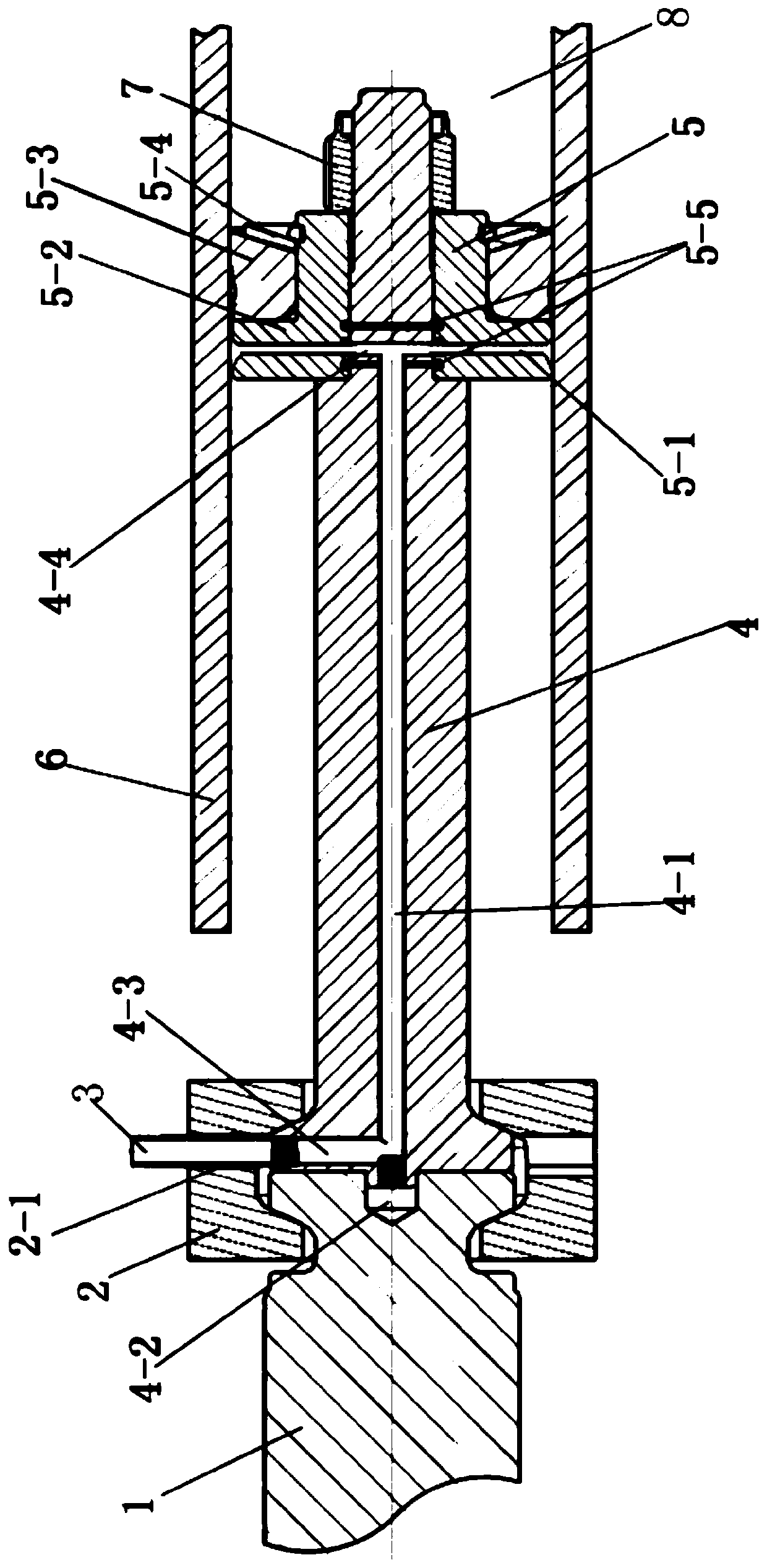
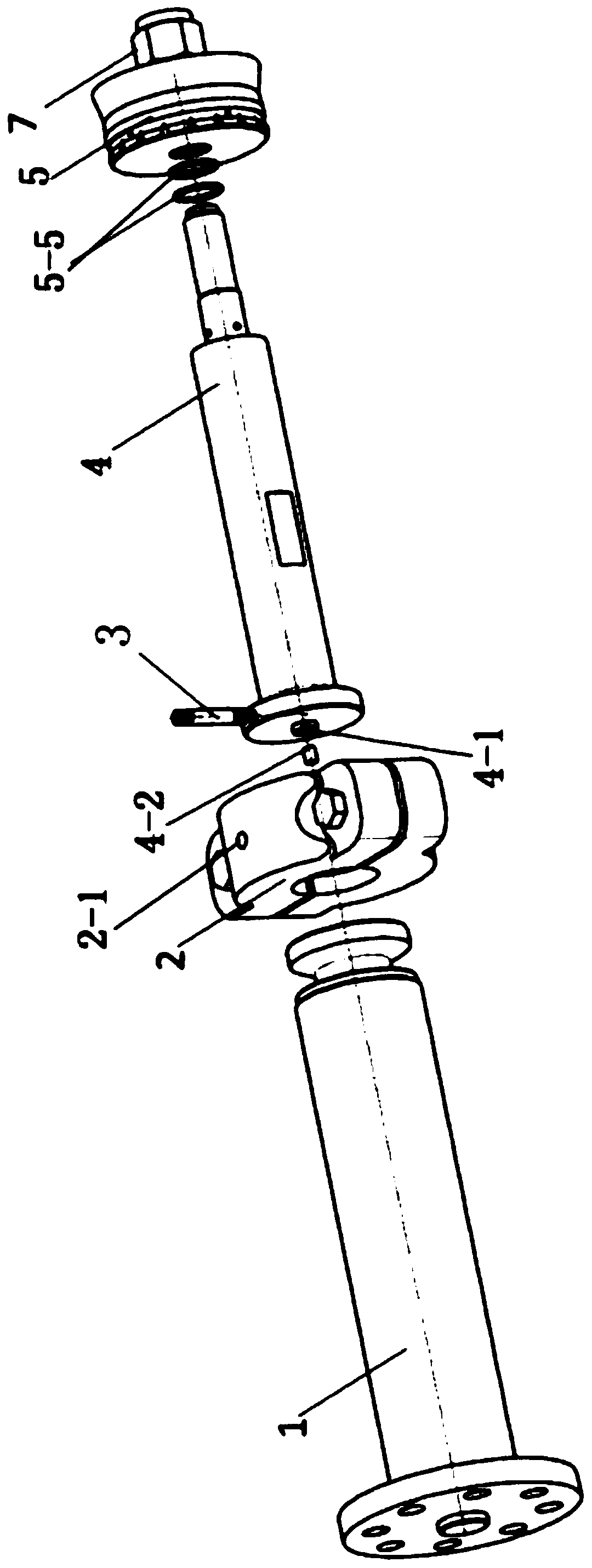
[0031] Drilling pump piston follow-up spray cooling structure, such as figure 1 and figure 2 As shown, it includes the middle tie rod 1, one end of the middle tie rod 1 is connected with one end of the piston rod 4, the middle tie rod 1 and the piston rod 4 are coaxially connected through the clamp 2, and the other end of the piston rod 4 is coaxially connected with the piston assembly 5 , the piston assembly 5 can perform piston movement in the matching cylinder liner 6;

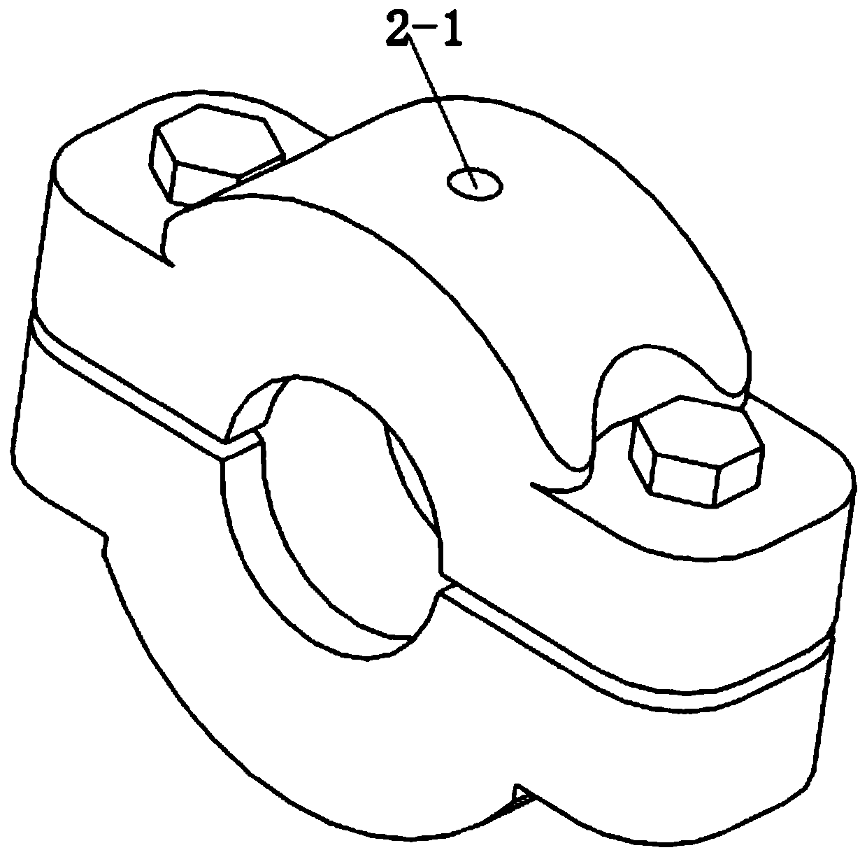
[0032] One side of the clamp 2 is provided with a connection hole 2-1, and the inside of the piston rod 4 is provided with a coolant flow channel. The clamp connection hole 2-1 communicates with one end of the coolant flow channel. There is an assembly flow channel 5-1 facing inward, and the assembly flow channel 5-1 communicates with the other end of the piston rod coo...


PUM


Abstract

The invention provides a follow-up spray cooling structure of a piston of a drilling pump. The follow-up spray cooling structure comprises a piston rod, wherein one end of the piston rod is coaxiallyconnected with the middle pull rod, the other end of the piston rod is coaxially connected with a piston assembly, and the piston assembly can do piston motion in a matched cylinder sleeve; a coolingliquid flow channel is formed in the piston rod, one end of the cooling liquid flow channel is formed in the outer wall of the piston rod, an assembly flow channel is formed in the piston assembly from the outer circumference face inwards, and the other end of the cooling liquid flow channel of the piston rod is communicated with the assembly flow channel. The follow-up spray cooling structure ofthe piston of the drilling pump solves the problem that the cooling efficiency is poor due to a large amount of cooling liquid splashing in an existing cooling structure.

Description

technical field [0001] The invention belongs to the technical field of petroleum drilling equipment, and relates to a piston follow-up spray cooling structure of a drilling pump. Background technique [0002] At present, in the field of oil drilling and production equipment, drilling pumps are widely used as supporting equipment for oil drilling rigs. The drilling pump pumps and pressurizes the drilling fluid through the reciprocating movement of the piston in the cylinder liner. When the pressure is high, the contact area between the piston and the cylinder liner is in the harsh working condition of high temperature and high pressure. In addition, because the drilling fluid contains impurities and even hard particles, when the piston reciprocates, these small particles can easily strain the contact surface and aggravate the problem. The wear of the piston and the cylinder liner, if the cooling between the friction surfaces is not good, it may cause the piston rubber to be ...

Claims


Application Information

Patent Timeline
IPC IPC(8): F04B53/08F04B53/14
CPCF04B53/08F04B53/14F04B53/144
Inventor 李永飞曾兴昌刘虎何根良董超群李鹏举
Owner BAOJI PETROLEUM MASCH CO LTD
Learn More