Torque shunting speed reducer and application method, detection and control system thereof

A control system and reducer technology, applied in linear/angular velocity measurement, speed/acceleration/impact measurement, mechanical equipment, etc. Reliability and stability, increased service life, avoid the effect of excessive temperature

Inactive Publication Date: 2019-08-23
YANCHENG INST OF TECH
View PDF0 Cites 1 Cited by
  • Summary
  • Abstract
  • Description
  • Claims
  • Application Information

AI Technical Summary

Problems solved by technology

[0005] (1) The existing reducer can bear limited load. As the load increases, the internal parts of the reducer are prone to fatigue wear or fracture, and the service life is low
[0006] (2) The existing reducer control system cannot guarantee the stable operation of the equipment in the process of controlling the reducer
[0007] (3) When the gear transmission shaft in

Method used


Image

  • Torque shunting speed reducer and application method, detection and control system thereof
  • Torque shunting speed reducer and application method, detection and control system thereof
  • Torque shunting speed reducer and application method, detection and control system thereof

Examples


Embodiment Construction

[0048] In order to further understand the content, features and effects of the present invention, the following examples are given, and detailed descriptions are given below with reference to the accompanying drawings.

[0049] The structure of the present invention will be described in detail below in conjunction with the accompanying drawings.

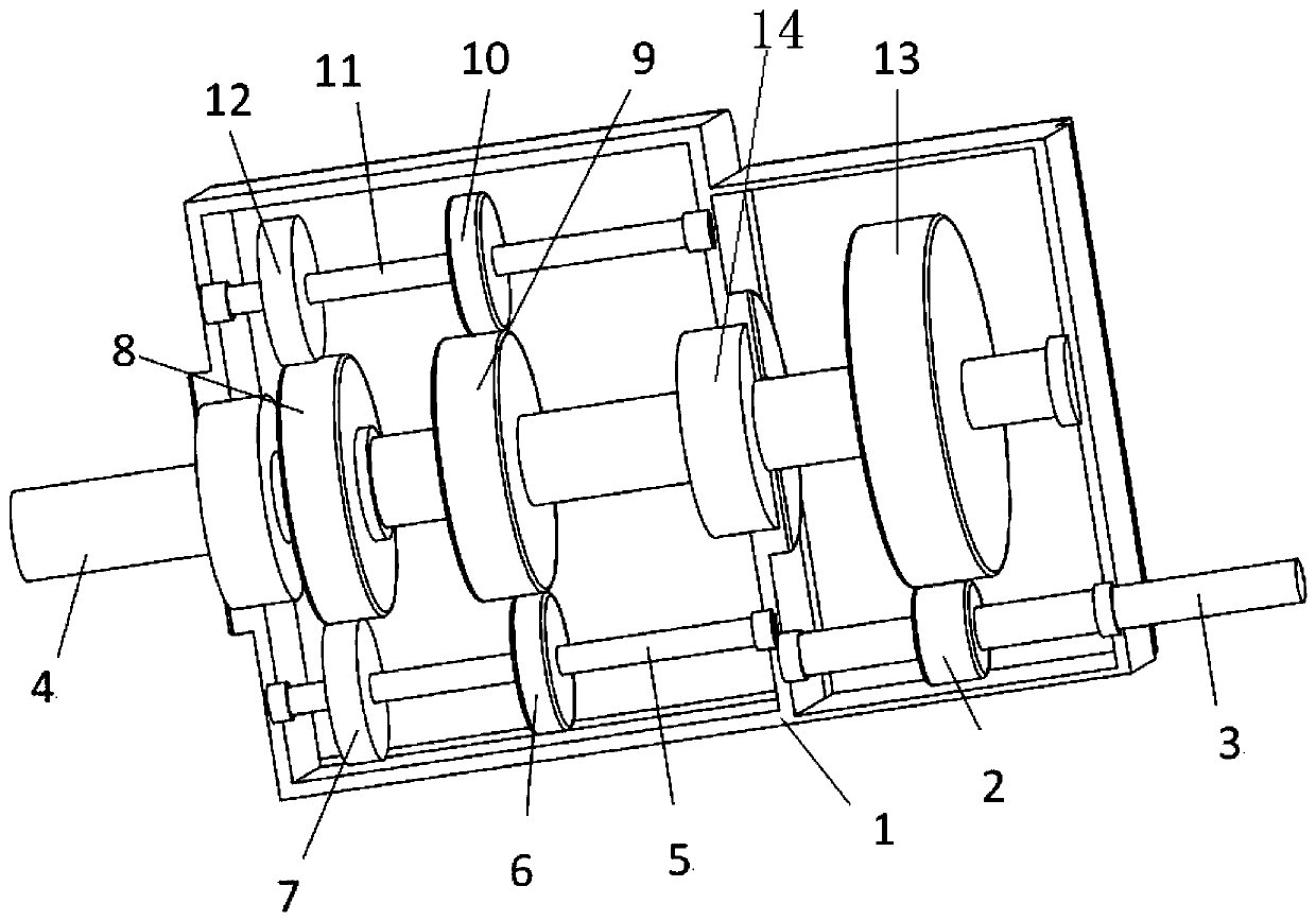
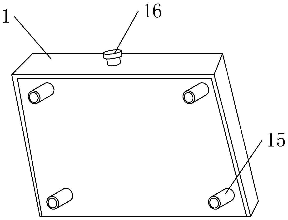
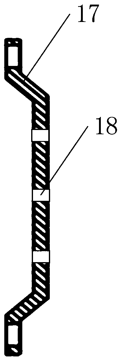
[0050] Such as Figure 1 to Figure 3 As shown, the torque split reducer provided by the embodiment of the present invention includes: reducer housing 1, input shaft spur gear 2, input shaft 3, output shaft 4, first split shaft 5, first split shaft first spur gear 6 , the second spur gear of the first diverter shaft 7, the first spur gear of the output shaft 8, the second spur gear of the output shaft 9, the first spur gear of the second diverter shaft 10, the second diverter shaft 11, the second straight gear of the second diverter shaft Gear 12, the third spur gear 13 of the output shaft, bearing 14, threaded fixing post 15, grease...


PUM


Abstract

The invention belongs to the technical field of speed reducers, and discloses a torque shunting speed reducer and an application method, a detection and control system thereof; the torque shunting speed reducer is provided with a speed reducer shell; the two ends of the inner part of the speed reducer shell are provided with an input shaft and an output shaft through bearings respectively, an input shaft straight gear is connected to the input shaft through a key, an output shaft third straight gear is fixed at one end of the output shaft through a key, the output shaft third straight gear ismeshed with the input shaft straight gear, an output shaft first straight gear and an output shaft second straight gear are fixed at the other end of the output shaft through keys, and a first shunting shaft and a second shunting shaft are fixed on the two sides of the output shaft through bearings respectively. According to the torque shunting speed reducer, the two shunting shafts are additionally arranged on the two sides of the output shaft, so that the rotating torque borne by the output shaft is effectively shunted to the straight gears on the two shunting shafts, the maximum rotating torque possibly borne by the output shaft is reduced, fatigue abrasion and damage possibly caused in the speed reducer are reduced, and the service life of the speed reducer is prolonged.

Description

technical field [0001] The invention belongs to the technical field of reducers, and in particular relates to a torque split reducer and its use method, detection and control system. Background technique [0002] The reducer is an independent component composed of gear transmission, worm transmission, and gear-worm transmission enclosed in a rigid shell. It is often used as a reduction transmission device between the prime mover and the working machine. It plays the role of matching speed and transmitting torque between prime mover and working machine or actuator, and is widely used in modern machinery. [0003] At present, as the load increases, the torque inside the reducer also increases. Due to the increase in torque, the gears and the main shaft are prone to fatigue wear and even fracture, which reduces the service life of the reducer; at the same time, the existing reducer In the process of controlling the reducer, the machine control system cannot guarantee the stabl...

Claims


Application Information

Patent Timeline
IPC IPC(8): F16H1/22F16H57/04G01B11/00G01K17/00G01P3/00
CPCF16H1/22F16H57/0412F16H57/0434G01B11/00G01K17/00G01P3/00
Inventor 郑雷董香龙曾勇宦海祥韦文东郑力志林煦航孙建鑫
Owner YANCHENG INST OF TECH
Why Eureka
Try Eureka