
Surface flashover experiment device

An experimental device and surface flashover technology are applied in the direction of measuring devices, material analysis through electromagnetic means, instruments, etc., which can solve the problems of high power supply voltage requirements and low safety, achieve good sealing effect, improve sealing effect, Avoid the effect of local excessive deformation

Pending Publication Date: 2019-08-23
ARMY ENG UNIV OF PLA
View PDF0 Cites 0 Cited by
  • Summary
  • Abstract
  • Description
  • Claims
  • Application Information

AI Technical Summary

Problems solved by technology

Considering that the voltage of flashover along the surface is generally tens of thousands or even hundreds of thousands of high voltage, the experiment has high requirements on the power supply voltage and low safety

Method used


Image

  • Surface flashover experiment device
  • Surface flashover experiment device
  • Surface flashover experiment device

Examples


Embodiment Construction

[0022] The standard parts used in the present invention can be purchased from the market, and the special-shaped parts can be customized according to the instructions and the accompanying drawings. The specific connection methods of each part adopt mature bolts, rivets, welding in the prior art , pasting and other conventional means, no longer described in detail here.

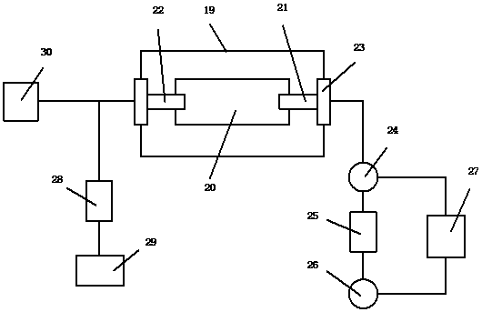
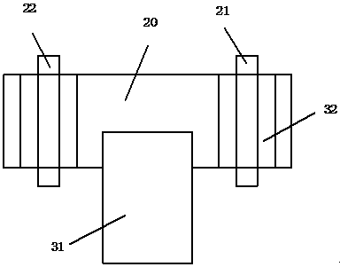
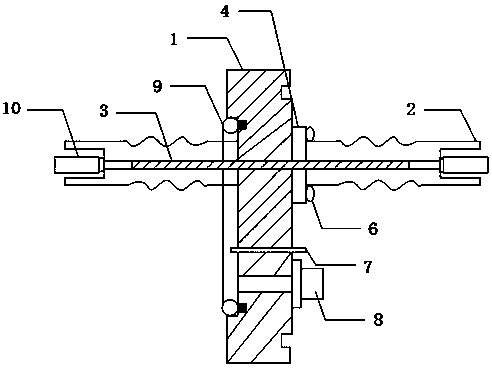
[0023] refer to Figure 1-7 , a specific embodiment of the present invention comprises a vacuum tank 19, a polytetrafluoroethylene platform 20 is installed in the vacuum tank 19, an anode 21 and a cathode 22 are fixed on the polytetrafluoroethylene platform 19, and the outlet ends of the anode 21 and the cathode 22 are passed through the method The blue mechanism 23 is fixed in the vacuum tank 19, the anode 21 is connected in series with a voltage test probe 24, a test resistor 25 and a current test coil 26, the voltage test probe 24 and the current test coil 26 are connected to an oscilloscope 27, and the cat...


PUM

PropertyMeasurementUnit
thicknessaaaaaaaaaa
electrical resistanceaaaaaaaaaa

Abstract

The invention discloses a surface flashover experiment device. The device includes a vacuum tank. A polytetrafluoroethylene platform is mounted in the vacuum tank. An anode and a cathode are fixed tothe polytetrafluoroethylene platform. Outlet ends of the anode and the cathode are fixed in the vacuum tank through a flange mechanism. The anode is connected in series with a voltage test probe, a test resistor and a current test coil. The voltage test probe and the current test coil are connected to an oscilloscope. The cathode is connected to a voltage source through a current-limiting resistor. The cathode is connected to an electrostatic potential dynamic tester. The surface flashover experiment device can improve the shortcomings of the prior art, facilitates a discharge experiment of aspacecraft surface insulating material, and is safe and reliable in use.

Description

technical field [0001] The invention relates to the technical field of surface discharge experiments on insulating materials on the surface of spacecraft, in particular to a flashover experiment device along the surface. Background technique [0002] During the operation of the spacecraft, the vacuum environment is its main working environment. In addition, environments such as plasma and solar radiation have a non-negligible impact on the safe operation of spacecraft, so spacecraft need to withstand different degrees of influence from different environments. The complex space electromagnetic environment determines that the charges accumulated on the spacecraft cannot be discharged in time, so the charged voltage on the surface of the spacecraft is often as high as tens of thousands of volts. Due to the difference in the structure of the surface devices of the spacecraft, the local electric field intensity is distorted. When the voltage reaches the discharge threshold of th...

Claims


Application Information

Patent Timeline
Patent Type & Authority Applications(China)
IPC IPC(8): G01N27/60
CPCG01N27/60
Inventor 孙永卫原青云周立栋范亚杰张希军杨洁王彪
Owner ARMY ENG UNIV OF PLA
Learn More