A Calculation Model of HVDC Transmission Lines Based on Distributed Resistance Parameters

A technology of transmission lines and high-voltage direct current, applied in the field of power systems, can solve problems such as increased ranging errors and achieve remarkable results

Active Publication Date: 2021-07-09
ELECTRIC POWER RESEARCH INSTITUTE OF STATE GRID SHANDONG ELECTRIC POWER COMPANY +1
View PDF8 Cites 0 Cited by
  • Summary
  • Abstract
  • Description
  • Claims
  • Application Information

AI Technical Summary

Problems solved by technology

[0005] The purpose of the present invention is to solve the problem that the inaccurate calculation model of the current high-voltage direct current transmission line leads to the increase of the ranging error, and proposes a calculation model of the high-voltage direct current transmission line based on distributed resistance parameters, and extracts the voltage and current of the measurement points at both ends of the line After the value is calculated, the voltage and current values ​​along the DC transmission line are calculated by using the line model that takes the distributed resistance into account, and then according to the fact that the first reverse traveling wave has not yet reflected after the fault, it is not affected by the frequency change of the reflection coefficient, and the fault characteristics are obvious. Calculate the reverse traveling wave current value along the DC transmission line, and finally calculate the modulus maximum value of the reverse traveling wave current through the stationary wavelet transform to improve the accuracy of the transmission line calculation model

Method used


Image

  • A Calculation Model of HVDC Transmission Lines Based on Distributed Resistance Parameters
  • A Calculation Model of HVDC Transmission Lines Based on Distributed Resistance Parameters
  • A Calculation Model of HVDC Transmission Lines Based on Distributed Resistance Parameters

Examples


Embodiment Construction

[0045] In order to make the objects, technical solutions, and advantages of the present invention, the technical solutions in the embodiments of the present invention will be described in contemplation in the embodiments of the present invention, and will be described in contemplation in the embodiment of the present invention. It is an embodiment of the present invention, not all of the embodiments, generally described and illustrated in the drawings herein, can be arranged and design in a variety of different configurations.

[0046] Therefore, the detailed description of the embodiments of the invention provided in the drawings are not intended to limit the scope of the invention, but only the selected embodiments of the present invention, based on the embodiments of the present invention, Field skilled in the art is the scope of the protected by the present invention without making creative labor.

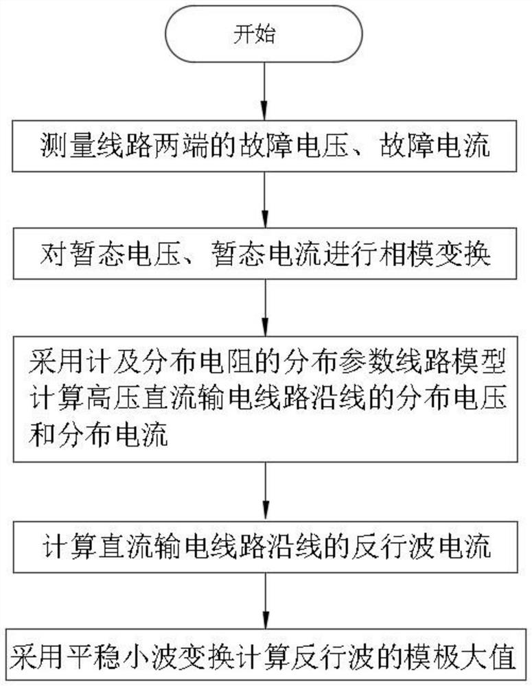
[0047] Refer to the attachment figure 1 The calculation model of the high volt...


PUM


Abstract

The invention discloses a high-voltage direct current transmission line calculation model based on distributed resistance parameters, which includes the following steps: ① Acquisition of fault voltage signals and current signals; ② Decoupling to obtain line mode components; The model calculates the voltage and current line mode components along the DC transmission line; ④ calculates the reverse traveling wave current along the DC transmission line; ⑤ uses the stationary wavelet transform to calculate the modulus maximum value of the reverse traveling wave current. In the present invention, after extracting the voltage and current values ​​at the measurement points at both ends of the line, the line model of the voltage and current along the DC transmission line is calculated by using the line model taking into account the distributed resistance, and then according to the reflection of the first reverse traveling wave, it is not affected by Influenced by the frequency variation of the reflection coefficient and the characteristics of obvious fault features, the reverse traveling wave current value along the DC transmission line is calculated, and finally the modulus maximum value of the reverse traveling wave current is calculated through the stationary wavelet transform to improve the accuracy of the calculation model of the transmission line.

Description

Technical field [0001] The present invention relates to the technical field of power systems, and more particularly to a high-voltage direct current transmission line calculation model based on distributed resistance parameters. Background technique [0002] In recent years, my country's high-voltage DC transmission project has been transported, based on the plan, reaching 36 DC projects by 2020, of which is more than 16 of the voltage grade DC projects in 200kV and above. Safety and stability of high-voltage DC transmission projects is of great significance to ensure the safety of the entire grid. When a high-voltage DC transmission line is faulty, it is necessary to find a fault cause, and determine the fault location. [0003] Due to the high-voltage DC radios, the distribution parameter characteristics of the transmission line is obvious, and the traditional centralized parameter model is far from satisfying the requirements of the fault ranging to the accuracy of the line mo...

Claims


Application Information

Patent Timeline
Patent Type & Authority Patents(China)
IPC IPC(8): G01R31/08
CPCG01R31/085G01R31/088
Inventor 李宽李玉敦史方芳尹欢欢杨超张婉婕刘萌赵斌超王永波黄秉青李聪聪麻常辉张国辉王昕
Owner ELECTRIC POWER RESEARCH INSTITUTE OF STATE GRID SHANDONG ELECTRIC POWER COMPANY
Why Eureka
Try Eureka