Eureka AIR delivers breakthrough ideas for toughest innovation challenges, trusted by R&D personnel around the world.

Volume holographic optical waveguide, manufacturing method thereof and color volume holographic optical waveguide

A manufacturing method and optical waveguide technology, which are applied in the field of optics, can solve problems such as the smaller field angle of outcoupled light, the decrease in brightness uniformity of the image observed by the human eye, and the uneven distribution of light.

Active Publication Date: 2022-02-25
SHENZHEN LOCHN OPTICS HI-TECH CO LTD
View PDF7 Cites 0 Cited by
  • Summary
  • Abstract
  • Description
  • Claims
  • Application Information

AI Technical Summary

Problems solved by technology

However, in this exposure method, the light totally reflected in different directions on the surface of the material also participates in the exposure of the required grating area, which results in a variety of complex grating structures being recorded in the three grating areas. The turning grating can only be exposed as a transmissive volume holographic grating, and its small angular bandwidth will limit the viewing angle of the final viewing image, resulting in a smaller viewing angle for the final outcoupling light
In addition, in the multiple groups of composite gratings, the transmissive volume holographic grating and the reflective volume holographic grating have different diffraction angle bandwidths for the light in the optical waveguide, resulting in uneven distribution of the outcoupled light in the eye box area, causing the human eye to observe the picture. The brightness uniformity of the

Method used


Image

  • Volume holographic optical waveguide, manufacturing method thereof and color volume holographic optical waveguide
  • Volume holographic optical waveguide, manufacturing method thereof and color volume holographic optical waveguide
  • Volume holographic optical waveguide, manufacturing method thereof and color volume holographic optical waveguide

Examples


Embodiment Construction

[0069] The present invention will be described in detail below in conjunction with specific embodiments. The following examples will help those skilled in the art to further understand the present invention, but do not limit the present invention in any form. It should be noted that those skilled in the art can make several modifications and improvements without departing from the concept of the present invention. These all belong to the protection scope of the present invention.

[0070] In order to facilitate the understanding of the present application, the present application will be described in more detail below in conjunction with the accompanying drawings and specific embodiments. Unless otherwise defined, all technical and scientific terms used in this specification have the same meaning as commonly understood by one of ordinary skill in the technical field of this application. The terms used in the description of the present application are only for the purpose of ...


PUM


Abstract

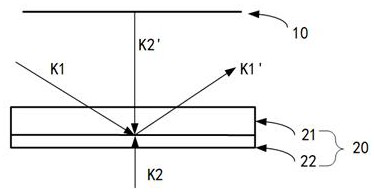
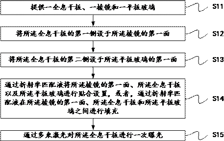
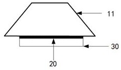
The embodiment of the invention provides a volume holographic optical waveguide, a manufacturing method thereof and a color volume holographic optical waveguide. The method comprises the following steps of: providing a holographic plate, a prism and plate glass; arranging a first side of the holographic plate on a first surface of the prism; arranging a second side of the holographic plate on a first surface of the plate glass; arranging the first surface of the prism, the holographic plate and the plate glass in an attached mode through refractive index matching liquid, or filling the space among the first surface of the prism, the holographic plate and the plate glass with the refractive index matching liquid; and performing primary exposure on the holographic plate through multiple beams of laser. According to the manufacturing method, when the volume holographic optical waveguide is used, a manufactured coupling-in grating, coupling-out grating and turning grating are all reflection-type volume holographic gratings, it can be avoided that multiple composite gratings are overlapped in needed gratings subsequently, and the field angle size and field brightness uniformity of the volume holographic optical waveguide are improved.

Description

technical field [0001] Embodiments of the present invention relate to the field of optical technology, and in particular to a volume holographic optical waveguide, a manufacturing method thereof, and a color volume holographic optical waveguide. Background technique [0002] In the augmented reality (Augmented Reality, AR) near-eye display system based on the volume holographic optical waveguide, the larger the field of view (Field of view, FOV) of the volume holographic optical waveguide, the larger the picture, so that the user can Get an immersive experience that enhances the viewing experience. In addition, reducing the volume and weight of the optical system (optical machine) is very important for the market application of AR display. [0003] In order to reduce the volume and weight of the optical machine, a two-dimensional pupil-expanding volume holographic optical waveguide is usually used. The optical diffraction part is composed of three grating areas, including t...

Claims


Application Information

Patent Timeline
IPC IPC(8): G02B6/10G02B27/01
CPCG02B6/10G02B27/0103
Inventor 杨鑫罗润秋宋强马国斌
Owner SHENZHEN LOCHN OPTICS HI-TECH CO LTD
Why Eureka
Eureka Blog
Learn More