
Array substrate, preparation method thereof, display panel and display device

An array substrate and substrate technology, which is applied to electrical components, electrical solid-state devices, circuits, etc., can solve the problems of large seams on the display screen, reduced display effect, and difficulty in opening glass through holes, etc. stitch, improve the display effect

Active Publication Date: 2019-08-23
BOE TECH GRP CO LTD
View PDF5 Cites 33 Cited by
  • Summary
  • Abstract
  • Description
  • Claims
  • Application Information

AI Technical Summary

Problems solved by technology

However, it is difficult to open through-glass holes after the glass substrate is equipped with a driving circuit, so that the glass substrate cannot be bent to reduce its frame
This leads to large seams in the large-size display screen spliced ​​by Micro LED screens, which reduces the display effect

Method used


Image

  • Array substrate, preparation method thereof, display panel and display device
  • Array substrate, preparation method thereof, display panel and display device
  • Array substrate, preparation method thereof, display panel and display device

Examples


Embodiment Construction

[0066] Example embodiments will now be described more fully with reference to the accompanying drawings. Example embodiments may, however, be embodied in many forms and should not be construed as limited to the examples set forth herein; rather, these embodiments are provided so that this disclosure will be thorough and complete, and will fully convey the concept of example embodiments to those skilled in the art. The described features, structures, or characteristics may be combined in any suitable manner in one or more embodiments. In the following description, numerous specific details are provided in order to give a thorough understanding of embodiments of the present disclosure.

[0067] In the drawings, the thicknesses of regions and layers may be exaggerated for clarity. The same reference numerals in the drawings denote the same or similar structures, and thus their detailed descriptions will be omitted.

[0068] The terms "a", "an" and "the" are used to indicate th...


PUM


Abstract

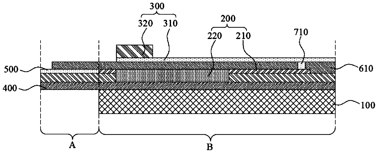
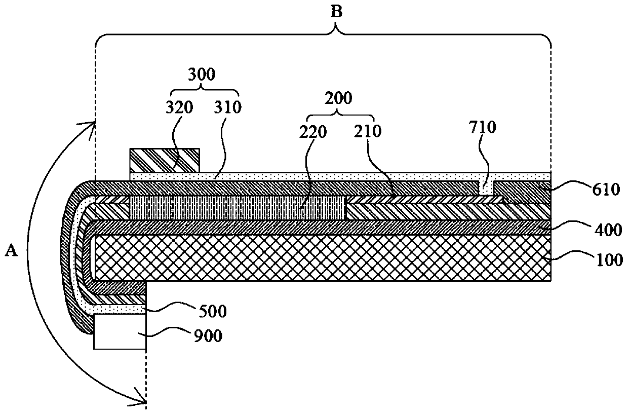
The invention provides an array substrate, a preparation method thereof, a display panel and a display device, and belongs to the technical field of display. The array substrate comprises a binding area and a non-binding area. The array substrate further comprises a rigid substrate, a driving circuit layer, a light emitting diode layer, a flexible substrate layer and a binding lead layer, whereinthe rigid substrate is arranged in the non-binding area; the driving circuit layer is arranged at one side of the rigid substrate; the light emitting diode layer is arranged at the side, which is awayfrom the rigid substrate, of the driving circuit layer; the flexible substrate layer is arranged in the binding area and located at the same side of the rigid substrate as the driving circuit layer;the binding lead layer is arranged at the side, which is away from the rigid substrate, of the flexible substrate layer, and the binding lead layer is electrically connected with the driving circuit layer; and the binding lead layer and the flexible substrate layer can be bent to the side, which is away from the driving circuit layer, of the rigid substrate along the edge of the rigid substrate. The array substrate can reduce the frame of the display panel.

Description

technical field [0001] The present disclosure relates to the field of display technology, and in particular to an array substrate and a manufacturing method thereof, a display panel and a display device. Background technique [0002] Micro LED (Micro Light Emitting Diode, miniature light-emitting diode) has excellent characteristics such as self-illumination, high luminous efficiency, high contrast, wide operating temperature range, long life, low power consumption, excellent barrier to water and oxygen, and fast response. , It is more and more widely used in the field of large-scale splicing. [0003] In the prior art, a glass substrate provided with a driving circuit can be used to drive the Micro LED to emit light, so as to realize the high resolution of the Micro LED screen. However, it is difficult to open through-glass holes after the glass substrate is provided with the driving circuit, so that the frame of the glass substrate cannot be lowered by bending. This lead...

Claims


Application Information

Patent Timeline
Patent Type & Authority Applications(China)
IPC IPC(8): H01L27/15
CPCH01L27/156H01L25/167H01L33/0066H01L33/62H01L33/005H01L2933/0066
Inventor 孟柯崔强伟刘超王莉莉汪楚航初宇天龚林辉
Owner BOE TECH GRP CO LTD
Learn More