
Display panel and display device

A technology for display panels and display areas, which is applied to semiconductor devices, electrical components, circuits, etc., can solve problems such as affecting the sintering uniformity of the encapsulant 3', easy wrinkles in the encapsulant 3', and uneven height of the encapsulant 3'. , to achieve uniform melting degree by heating, improve curing effect, and improve the effect of high uniformity

Active Publication Date: 2021-09-07
WUHAN TIANMA MICRO ELECTRONICS CO LTD +1
View PDF0 Cites 0 Cited by
  • Summary
  • Abstract
  • Description
  • Claims
  • Application Information

AI Technical Summary

Problems solved by technology

In the prior art, based on the arrangement of the negative power signal line 1', there will be a large overlap between the negative power signal line 1' and the fan-out wiring 2' in a local area. The film layer formed by stacking the power signal line 1' and the fan-out line 2' is not flat, and there is a large height difference between the area where the negative power signal line 1' is located and others, which makes the height of the encapsulation glue 3' covered on it uneven. , when the encapsulation adhesive 3' is melted and solidified, the deformation and stress caused by the thermal expansion and contraction of the encapsulation adhesive 3' at different positions are different, so that the encapsulation adhesive 3' is prone to wrinkle at the position with high stress, which reduces the reliability of the encapsulation ; On the other hand, when the encapsulation glue 3' is sintered by laser, it is blocked by the negative power signal line 1', and the reflection path of the laser in a local area is too short, which is obviously different from the reflection path in other areas, which affects the encapsulation glue 3 'The sintering uniformity, the packaging glue 3' is prone to cracks in high temperature and high humidity environment, resulting in package failure

Method used


Image

  • Display panel and display device
  • Display panel and display device
  • Display panel and display device

Examples


Embodiment Construction

[0030] In order to better understand the technical solutions of the present invention, the embodiments of the present invention will be described in detail below in conjunction with the accompanying drawings.

[0031] It should be clear that the described embodiments are only some of the embodiments of the present invention, not all of them. Based on the embodiments of the present invention, all other embodiments obtained by persons of ordinary skill in the art without creative efforts fall within the protection scope of the present invention.

[0032] Terms used in the embodiments of the present invention are only for the purpose of describing specific embodiments, and are not intended to limit the present invention. As used in the embodiments of the present invention and the appended claims, the singular forms "a", "said" and "the" are also intended to include the plural forms unless the context clearly indicates otherwise.

[0033] It should be understood that the term "an...


PUM


Abstract

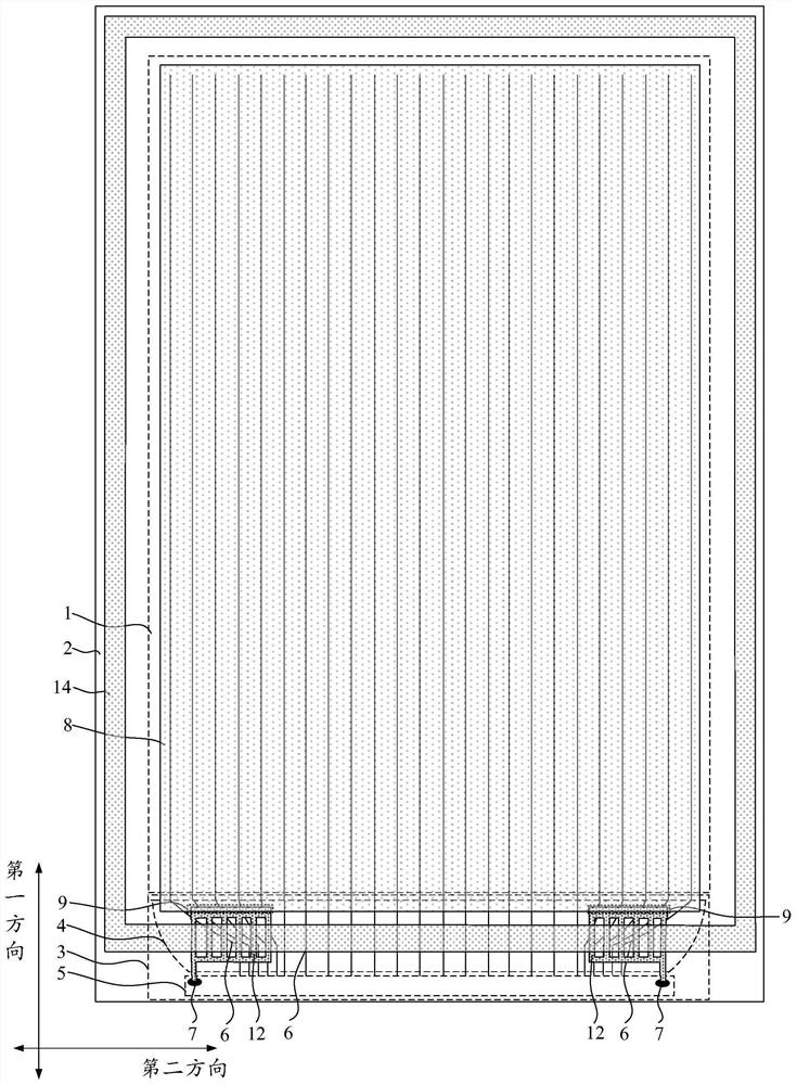
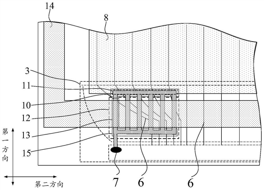
Embodiments of the present invention provide a display panel and a display device, relate to the field of display technology, and improve the packaging effect and reliability of the display panel. The display panel includes: a display area and a non-display area, the non-display area includes the lower step area, the lower step area includes the fan-shaped area and the bonding area, the fan-out area is provided with fan-out wiring, and the bonding area is provided with a negative power pad; layer, the cathode layer includes a cathode connection part located in the lower step area; a negative power bus located in the lower step area; the lower step area also includes a cathode contact area, and the negative power bus is connected to the cathode connection part in the cathode contact area; the lower step area There is a negative power connection part, and the negative power connection part and the fan-out wiring are arranged in different layers, and the negative power connection part is electrically connected to the negative power bus and a negative power pad; the negative power connection part includes a plurality of edge The first connecting parts extending in the first direction and arranged along the second direction have intervals between two adjacent first connecting parts.

Description

【Technical field】 [0001] The present invention relates to the field of display technology, in particular to a display panel and a display device. 【Background technique】 [0002] In order to prevent water and oxygen from corroding the devices in the display panel, an encapsulation glue is usually provided in the display panel. During the encapsulation process, the encapsulation glue is irradiated with laser to make it melt and solidify, so as to realize the encapsulation of the display panel. [0003] Usually, the non-display area of ​​the display panel includes the lower step area, such as figure 1 as shown, figure 1 It is a partial cross-sectional view of a display panel in the prior art. The lower step area is provided with a negative power signal line 1' and a fan-out line 2', and the fan-out line 2' is arranged in different layers. In the prior art, based on the arrangement of the negative power signal line 1', there will be a large overlap between the negative power s...

Claims


Application Information

Patent Timeline
Patent Type & Authority Patents(China)
IPC IPC(8): H01L27/32H01L51/52
CPCH10K59/131H10K50/844
Inventor 刘海民熊志勇范刘静
Owner WUHAN TIANMA MICRO ELECTRONICS CO LTD
Learn More