A Miniaturized and Compact Tri-Band Antenna

A three-band, compact technology, applied in the direction of antenna, leaky waveguide antenna, antenna grounding switch structure connection, etc., can solve the problem of narrow bandwidth of electrically small antenna, and achieve the effect of high frequency bandwidth, compact structure and reduced operating frequency band

Active Publication Date: 2020-12-29
UNIV OF ELECTRONICS SCI & TECH OF CHINA
View PDF9 Cites 0 Cited by
  • Summary
  • Abstract
  • Description
  • Claims
  • Application Information

AI Technical Summary

Problems solved by technology

The invention can effectively improve the problem of the narrow bandwidth of the existing electrically small antenna, and also has the advantages of compact structure and high frequency bandwidth.

Method used


Image

  • A Miniaturized and Compact Tri-Band Antenna
  • A Miniaturized and Compact Tri-Band Antenna
  • A Miniaturized and Compact Tri-Band Antenna

Examples


Embodiment Construction

[0024] The present invention will be further described in detail below in conjunction with specific embodiments.

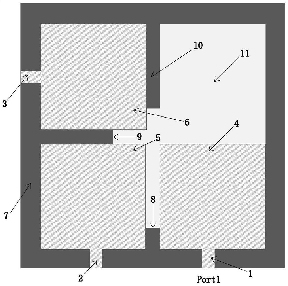
[0025] Such as figure 1 As shown, the miniaturized compact triple-band antenna proposed in this paper includes a square dielectric substrate (11), three square radiators (4, 5, 6) arranged on the front of the dielectric substrate, three microstrip lines (1, 2 , 3), the annular radiator (7) and three open lines (8, 9, 10) arranged on the back of the dielectric substrate. The side length of the square dielectric substrate (11) is S=26.4mm, and it is made of FR4 material with a dielectric constant of 4.6 and a thickness of 1mm.

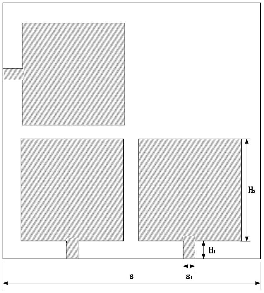
[0026] Such as figure 2 As shown, the three square radiators are the first monopole, the second monopole, and the third monopole with the same size, and the side length is H 2 =10.9mm, the side size determines the position of the antenna's high-frequency resonance frequency point and the offset of the low-frequency resonance point.

[0...


PUM

PropertyMeasurementUnit
lengthaaaaaaaaaa
thicknessaaaaaaaaaa
lengthaaaaaaaaaa

Abstract

The invention discloses a miniaturized and compact three-band antenna, which belongs to the technical field of antennas. The antenna includes a rectangular dielectric substrate, three rectangular radiators and three microstrip lines arranged on the front of the dielectric substrate, and an annular radiator and three open lines arranged on the back of the dielectric substrate. The antenna is excited by the microstrip line, using three monopoles with the same shape and electromagnetic characteristics and a modified ring structure for radiation, and loading the open line and the microstrip line on the upper and lower sides of the dielectric substrate. By adjusting the open line and The length of the microstrip line can achieve better impedance matching. The invention can effectively improve the problem of narrow bandwidth of the existing electric small antenna, and also has the advantages of compact structure, high frequency bandwidth and the like.

Description

technical field [0001] The invention belongs to the technical field of antennas, and in particular relates to a miniaturized and compact three-band patch antenna with electrically small characteristics. Background technique [0002] Wireless communication technology is one of the fastest-growing fields in the contemporary era. These technologies have already been used in systems such as Bluetooth headsets, laptop computers, Beidou positioning, and security sensors. As the economy develops, people's requirements for these wireless communication devices also increase. Due to the advantages of easy portability, simple installation, and small size, miniaturized devices are favored by people in daily office and home use. As an essential part of wireless systems, antennas have drawn much attention from designers of miniaturized systems. At the same time, there are more and more types of modern office and household equipment, and their uses are becoming wider and wider, so the re...

Claims


Application Information

Patent Timeline
Patent Type & Authority Patents(China)
IPC IPC(8): H01Q1/38H01Q1/50H01Q5/307H01Q5/50H01Q13/20
CPCH01Q1/38H01Q1/50H01Q13/206H01Q5/307H01Q5/50
Inventor 洪劲松邓焱陈执戬李雪飞周维思
Owner UNIV OF ELECTRONICS SCI & TECH OF CHINA
Why Eureka
Try Eureka