
Driving circuit of synchronous rectifier

A drive circuit and synchronous rectification technology, which is applied to electrical components, output power conversion devices, DC power input conversion to DC power output, etc., can solve problems such as circuit component damage, isolation converter startup failure, etc., to avoid misleading general effect

Active Publication Date: 2019-08-23
CHENGDU MONOLITHIC POWER SYST
View PDF6 Cites 3 Cited by
  • Summary
  • Abstract
  • Description
  • Claims
  • Application Information

AI Technical Summary

Problems solved by technology

At this time, since the drive circuit controlling the synchronous rectification device has not yet established the required drive level, the pull-down impedance of the control terminal of the synchronous rectification device (for example, when the synchronous rectification device is a MOSFET, the pull-down impedance of its gate) Very large (for example, it can reach the mega-ohm level), so the noise signal is easily coupled to the control terminal of the synchronous rectification device and causes the synchronous rectification device to turn on
Once this happens, since the primary switching device and the synchronous rectification device are turned on at the same time, it will not only cause the isolation converter to fail to start, but even cause unexpected consequences such as damage to circuit components.

Method used


Image

  • Driving circuit of synchronous rectifier
  • Driving circuit of synchronous rectifier
  • Driving circuit of synchronous rectifier

Examples


Embodiment Construction

[0023] Specific embodiments of the present disclosure will be described in detail below, and it should be noted that the embodiments described here are only for illustration, and are not intended to limit the present disclosure. On the contrary, the disclosure is intended to cover various alternatives, modifications and equivalents as defined within the spirit and scope of the disclosure as defined by the appended claims. In the following description, numerous specific details are set forth in order to provide a thorough understanding of the present disclosure. However, it will be understood by those of ordinary skill in the art that the present disclosure may be practiced without these specific details. In some other embodiments, well-known schemes, processes, components, circuits or methods are not described in detail in order to highlight the gist of the present disclosure.

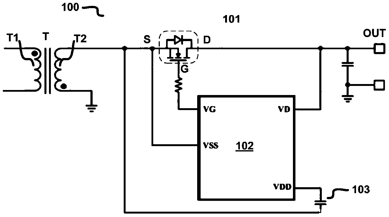
[0024] figure 1 A schematic circuit structure diagram of a synchronous rectification circuit 100 ...


PUM


Abstract

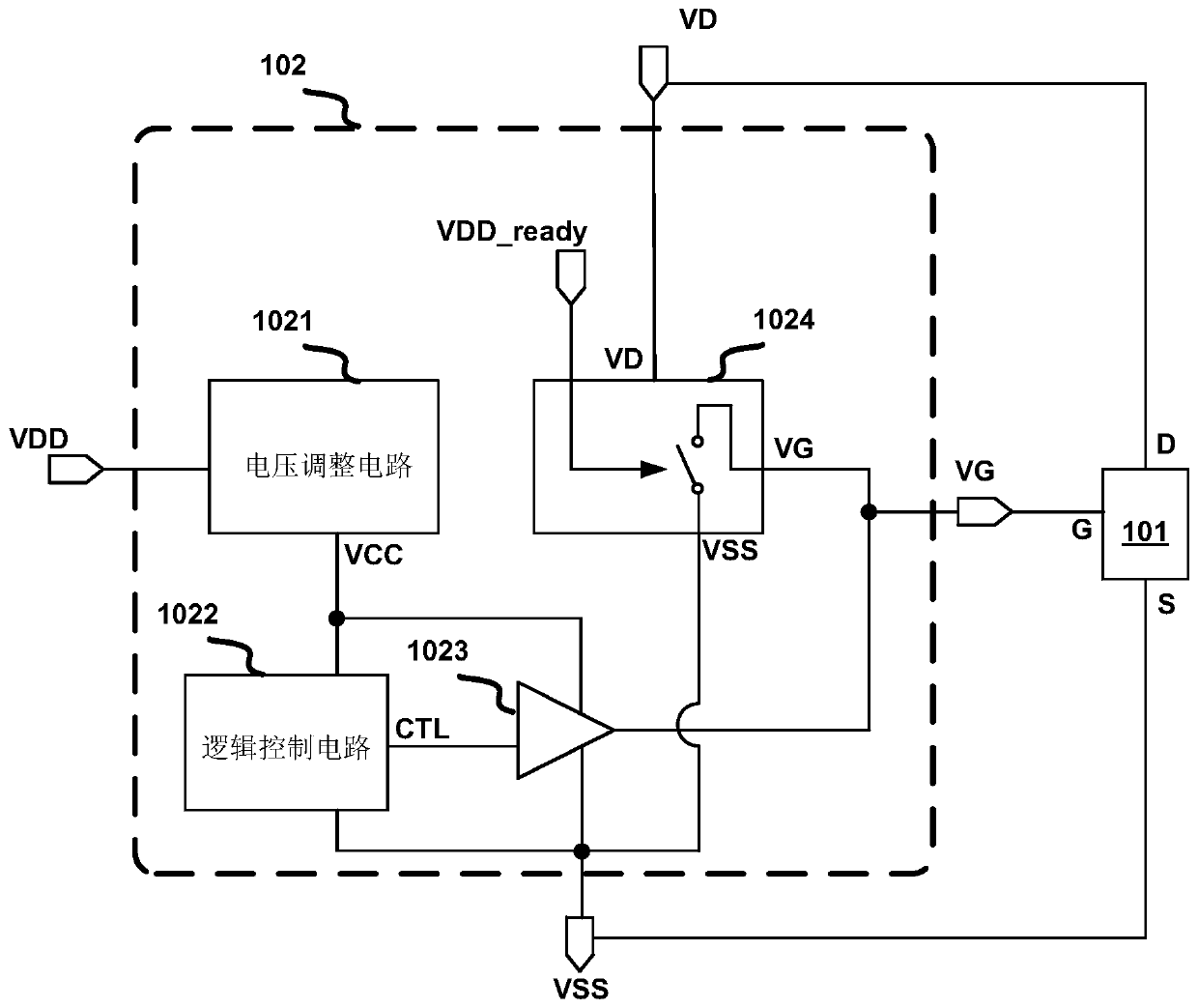
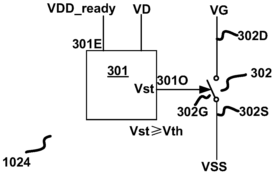
The embodiment of the invention discloses a driving circuit of a synchronous rectifier. The driving circuit comprises a controllable clamping circuit. The first end of the controllable clamping circuit is coupled to the first end of the synchronous rectifier, the second end of the controllable clamping circuit is coupled to the second end of the synchronous rectifier, the third end of the controllable clamping circuit is coupled to the control end of the synchronous rectifier, and the control end of the controllable clamping circuit is used for receiving the potential indication signal from the power supply end of the driving circuit. When the potential indication signal indicates that the potential of the power supply terminal of the driving circuit is not established, the controllable clamping circuit connects the third end of the controllable clamping circuit with the second end of the controllable clamping circuit based on the potential of the first end of the controllable clampingcircuit, thereby keeping the synchronous rectifier off and preventing mistaken conduction caused by coupling the noise signal to the control end of the synchronous rectifier.

Description

technical field [0001] Embodiments of the present disclosure relate to an electronic circuit, in particular to a driving circuit for a synchronous rectification device. Background technique [0002] Synchronous rectification devices can be used in various applications, such as secondary switching devices for isolated converters such as resonant converters and flyback converters. When the isolation converter just starts / starts to work, when the primary side switching device is turned on to form a current path on the primary side, the voltage at both ends of the synchronous rectification device will increase due to mutual inductance on the secondary side (for example, the synchronous rectification device is MOSFET, the voltage across its drain-source increases). At this time, since the drive circuit controlling the synchronous rectification device has not yet established the required drive level, the pull-down impedance of the control terminal of the synchronous rectification...

Claims


Application Information

Patent Timeline
Patent Type & Authority Applications(China)
IPC IPC(8): H02M7/12H02M1/08
CPCH02M7/12H02M1/08H02M1/36H02M7/217H02M1/0045H02M3/33592
Inventor 冯林陈跃东
Owner CHENGDU MONOLITHIC POWER SYST
Learn More